OSPF
Transport
OSPF it a protocol of itself. What do I mean by that? Well, you know TCP and UDP. Those are well-known protocols used for communication by a lot of applications. Similarly OSPF is a protocol riding directly on top of IP. It has IP protocol number 89. EIGRP is also a protocol of itself, but BGP for example is not.
We can see the protocol number if we look at a capture of an OSPF packet:
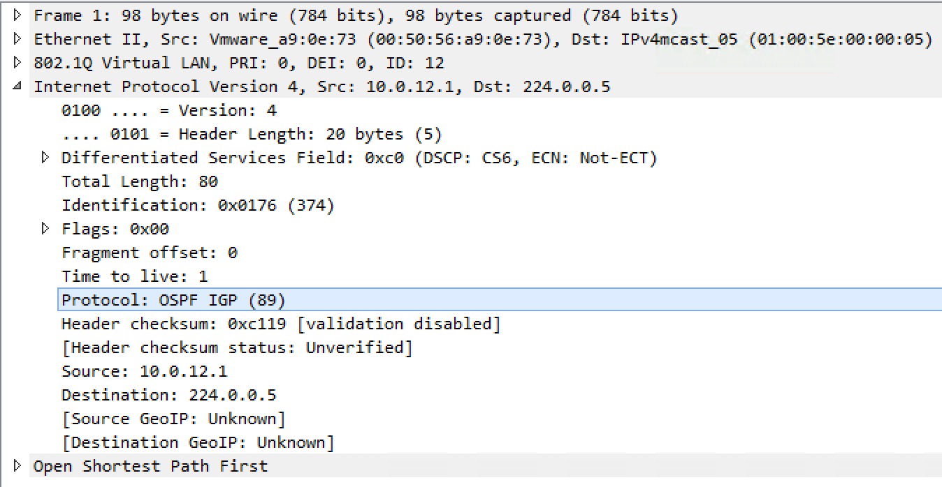
Besides showing the protocol number, we also see the IP address OSPF is using. The following IP addresses are well-known and reserved for OSPF, by IANA:
- 224.0.0.5
- All SPF routers on this segment
- 224.0.0.6
- All DR/BDR routers on this segment
Network Types
OSPF has these interface network types:
- Broadcast
- ARPA (Ethernet)
- Hello: 10
- DR election
- Non-broadcast
- Frame-Relay,� ATM,� X.25
- Hello: 30
- DR election
- Point-to-point
- GRE/mGRE, HDLC, PPP
- Hello: 10
- Point-to-multipoint
- Hello: 30
- Point-to-multipoint non-broadcast
- Hello: 30
- Loopback
- Advertises /32 regardless of configured subnet mask!
It is the interface encapsulation that dictates which network type is the default.
I didn’t bother to write about which ones uses multicast vs. unicast, because of this simple phrase:
“Non-broadcast needs neighbors”
This is the way I remember which ones need a unicast neighbor configuration. And by the way, you only need to configure the neighbor in one side – the other will respond and they establish an adjacency.
The Loopback advertising /32 regardless of subnet mask is easily fixed. Just change the network type to point-to-point on the Loopback interface, and the configured subnet mask is advertised.
Mixing Network Types
You can mix network types as long as they are compatible. What does it take to make the network types compatible? It’s actually rather simple. Of course you must be compliant first, meaning the stuff in the Hello packet must match to even consider the neighborship. Other than that it comes down to whether the two routers use a DR network type or not. If one side has broadcast network type configured, which requires a DR/BDR election, the other side must also have a DR-based network type configured – either broadcast or non-broadcast. If they don’t you’ll end of with two different views of the LSDB, because the DR will originate a Type 2 LSA with no information of the other router as an attached node to the segment. This causes reachability issues. Recent IOS versions will actually warn you about this:
! OSPF Log output:
%OSPF-4-NET_TYPE_MISMATCH: Received Hello from 1.1.1.1 on GigabitEthernet1.14 indicating a potential
network type mismatch
Note I didn’t need to turn on debugging to see this – just logging (warning level). And also note that you’ll only see this output on the router that does not have a DR-based network configuration. Why is this? Well, since it has a network type that will not elect a DR, it will not expect a Type 2 LSA to be originated by the adjacent router on this interface. This is how it knows something is wrong.
You can also see the issue in the router LSA of the neighbor on the router configured for P2P.
! R1 LSDB for R2's router LSA:
R1#sh ip ospf database router 2.2.2.2

            OSPF Router with ID (1.1.1.1) (Process ID 1)

                Router Link States (Area 0)

  Adv Router is not-reachable in topology Base with MTID 0
  LS age: 87
  Options: (No TOS-capability, DC)
  LS Type: Router Links
  Link State ID: 2.2.2.2
  Advertising Router: 2.2.2.2
  LS Seq Number: 80000015
  Checksum: 0x19C5
  Length: 36
  Number of Links: 1

    Link connected to: a Transit Network
      (Link ID) Designated Router address: 10.0.12.2
      (Link Data) Router Interface address: 10.0.12.2
       Number of MTID metrics: 0
         TOS 0 Metrics: 1

R1#
Here it is telling us that Adv Router is not reachable in the topology.
Adjacencies
To become adjacent (meaning establish a FULL neighbor) these fields of the Hello packet must match:
- Hello timer
- Dead timer
- Area number
- Flags
- E-bit (Normal (1) or Stub (0))
- N-bit (NSSA)
- Authentication
- MTU
- Subnet mask
- Not for P2P/P2M [non-broadcast]!
Here is a capture of the Hello packet:
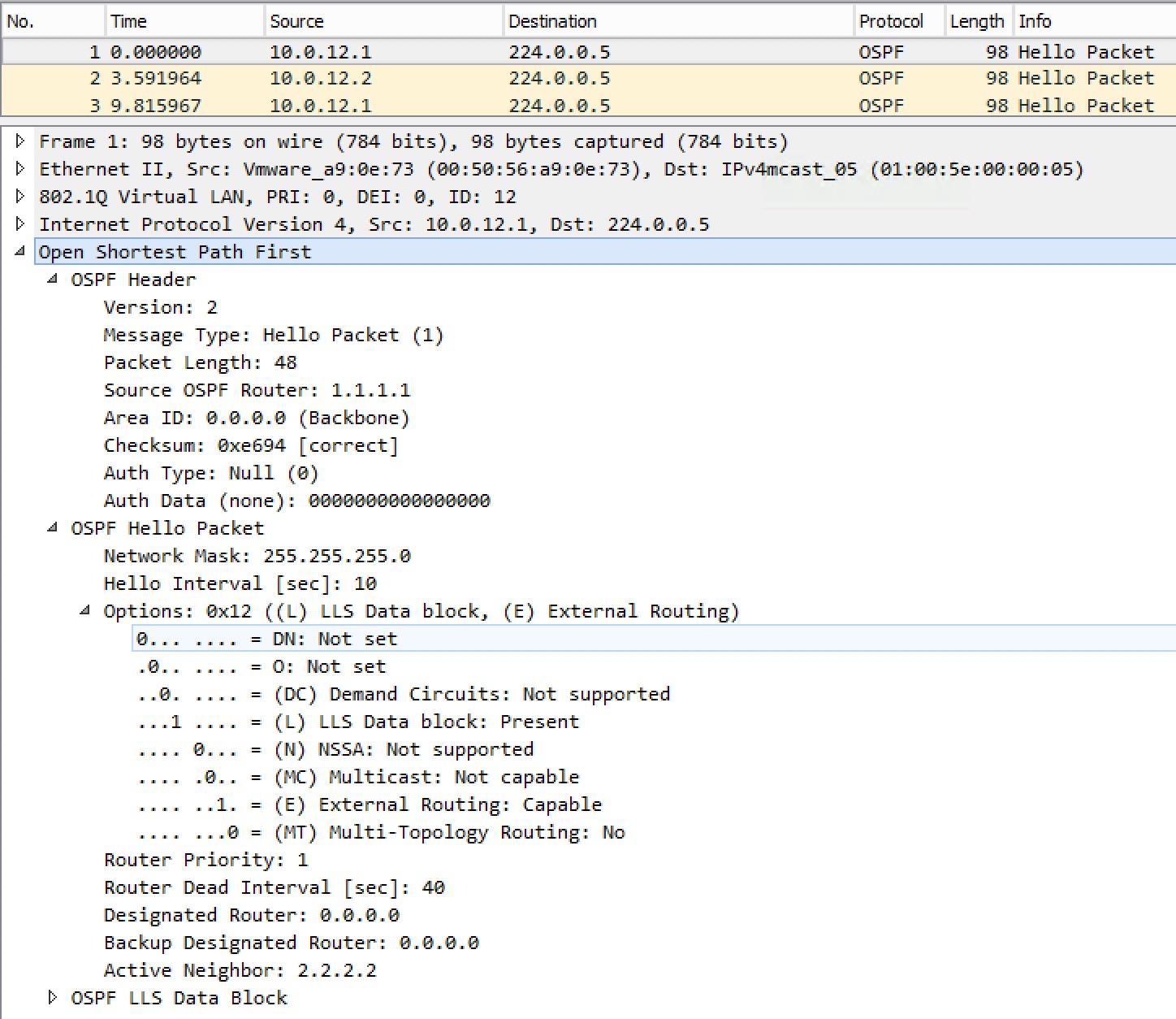
For DR-based network types, you only become adjacent with the DR and BDR – the DROTHER routers you’ll only become neighbors with (we see each other’s RIDs – 2WAY).
Besides the above fields that must match, the RIDs must be unique, or you’ll receive the following debug output:
! debug ip ospf adj output:
%OSPF-4-DUP_RTRID_NBR: OSPF detected duplicate router-id 1.1.1.1 from 10.0.14.4 on interface GigabitEthernet1.14
If you accidentally configure an incorrect subnet mask in one side of the link, meaning the two routers are not on the same subnet, you’ll see this debug output:
! debug ip ospf hello output:
OSPF-1 ADJ Gi1.14: Rcv pkt from 10.0.14.4, area 0.0.0.0 : src not on the same network
Why do I even see these messages, when they are on different subnets? In this case the routers use multicast to discover each other, meaning the link local multicast address reserved for OSPF, 224.0.0.5. The router knows the other end is in a different subnet because it checks the source IP of the Hello packet and compares it to its own configured subnet. If they do not match, they can’t unicast updates to each other which is required for FULL adjacency. Also for non-P2P/P2M adjacencies, meaning broadcast and non-broadcast, you will receive this debug output, if the subnet masks differ between the neighbors:
! R1 debug ip ospf hello output:
OSPF-1 HELLO Gi1.12: Mismatched hello parameters from 10.0.12.2
OSPF-1 HELLO Gi1.12: Dead R 40 C 40, Hello R 10 C 10 Mask R 255.255.255.192 C 255.255.255.0
Here the received ® mask is 255.255.255.192 and our configured © mask is 255.255.255.0. The adjacency will not form! You will not even see the neighbor in the neighbor table! The reason for this is that with broadcast and non-broadcast it is expected that more than two routers will become neighbors and therefore they should share a common subnet.
If you are changing network types, OSPF will notify you when you have an invalid configuration. Take a look at this:
! R2 OSPF output after changing from non-broadcast to broadcast:
%OSPF-4-CFG_NBR_INVALID_NET_TYPE: Can not use configured neighbor 10.0.12.1 on GigabitEthernet1.12. Neighbor command only allowed on NBMA and P2MP networks
This is because R2 was previously configured for non-broadcast and still has the neighbor statement under the OSPF process.
Area Types
The type of area is set in the Hello. You have these available area types with OSPF:
- Normal
- Stub
- NSSA
The normal area is just enabling OSPF on an interface without further configuration. With stub area types – either stub or NSSA – we always block LSA Type 5 and therefore also LSA Type 4. So you’ll never see O E1 or O E2 in the routing table of an internal OSPF router in a stub area – regardless of stub area type.
Let’s have a look at the differences between stub and NSSA.
Stub Area
Firstly let’s look at the requirements of a stub area.

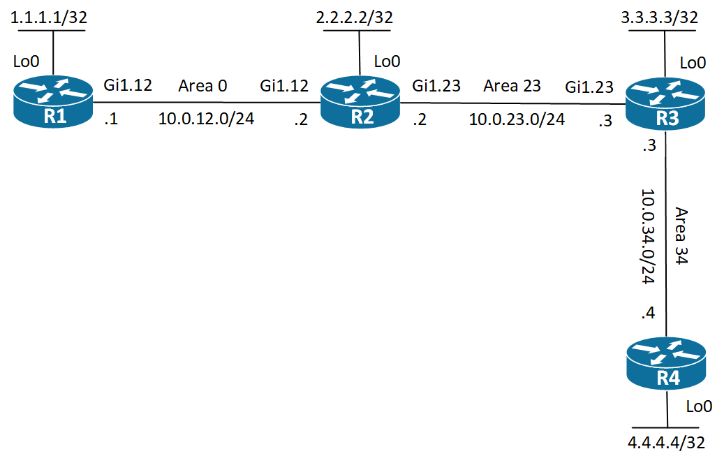
Right now R1 and R2 are configured for Area 0 on their Gi1.12 link and are adjacent.
! R1 Area 0
R1#sh ip ospf interface brief
Interface     PID    Area       IP Address/Mask   Cost   State  Nbrs F/C
Gi1.12.         1    0          10.0.12.1/24      1      P2P    1/1
R1#
R1#sh ip ospf neighbor gi1.12
Neighbor ID    Pri    State       Dead Time     Address       Interface
2.2.2.2          0    FULL/ -      00:00:34     10.0.12.2     GigabitEthernet1.12
R1#
Let’s try to configure the stub feature:
! R1 stub configuration:
R1(config)#router ospf 1
R1(config-router)#area 0 stub
% OSPF: Backbone can not be configured as stub area
R1(config-router)#
OK! So the backbone area (area 0) cannot be a stub area! So this is the first requirement. I’ll add R3 to the picture:
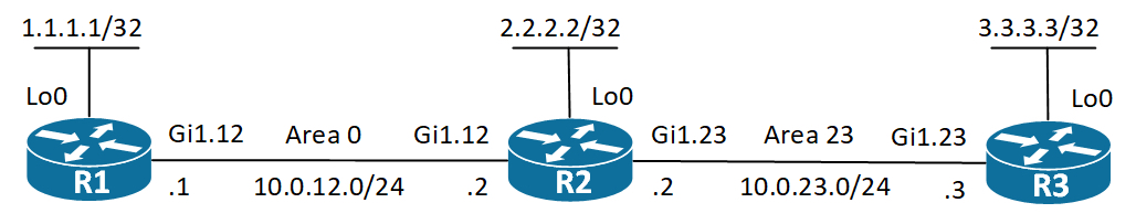
I’ve also added some Loopback interfaces to inject some prefixes into the topology. And I’ve configured � area 23 as a normal area between R2 and R3.
Let’s convert area 23 to a stub area and see what happens. I’ll start with R2:
! R2 stub configuration:
R2(config)#router ospf 1
R2(config-router)#area 23 stub
R2(config-router)#
%OSPF-5-ADJCHG: Process 1, Nbr 3.3.3.3 on GigabitEthernet1.23 from FULL to DOWN, Neighbor Down: Adjacency forced to reset
R2(config-router)#
The adjacency to R3 goes down immediately as area has been turned in to a stub area. Why is that? Let’s debug and also do a capture of the Hello packets.
! Debug on R2:
R2#deb condition interface gi1.23
R2#deb ip ospf hello
OSPF hello debugging is on
R2#
OSPF-1 HELLO Gi1.23: Rcv hello from 3.3.3.3 area 23 10.0.23.3
OSPF-1 HELLO Gi1.23: Hello from 10.0.23.3 with mismatched Stub/Transit area option bit
OSPF-1 HELLO Gi1.23: Send hello to 224.0.0.5 area 23 from 10.0.23.2
So we have a mismatched Stub/Transit area option bit. And in the capture we see this:
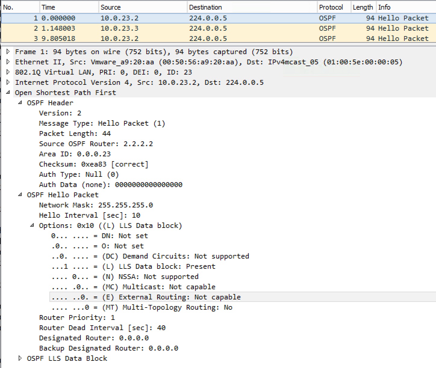
There is no actual “stub” flag per say, but like I wrote earlier about stub areas is that they are not capable of containing external information (Type 4/5 LSAs). This is why we see the (E) External Routing bit set to 0 (meaning Not capable). This hello packet is generated by R2 – R3 still tries to create a neighborship thinking area 23 is a normal area.
So if Type 4/5 LSAs are blocked, how do we reach destinations external to our OSPF domain? Let’s have a look.
I will start by injecting the connected Loopback0 interface of R1 via redistribution making it an O E2 (OSPF External Type 2) prefix:
! R1 inject Lo0 as external:
route-map con2ospf permit 10
 match interface Loopback0
!
router ospf 1
 redistribute connected subnets route-map con2ospf
We can verify on R2 looking at both the LSDB and the routing table:
! R2 verify injection of R1's Lo0:
R2#sh ip route ospf | be Gateway
Gateway of last resort is not set

     1.0.0.0/32 is subnetted, 1 subnets
O E2    1.1.1.1 [110/20] via 10.0.12.1, 00:03:26, GigabitEthernet1.12
R2#

R2#sh ip ospf database external 1.1.1.1

           OSPF Router with ID (2.2.2.2) (Process ID 1)

                 Type-5 AS External Link States

LS age: 240
Options: (No TOS-capability, DC, Upward)
LS Type: AS External Link
Link State ID: 1.1.1.1 (External Network Number )
Advertising Router: 1.1.1.1
LS Seq Number: 80000001
Checksum: 0x9BFC
Length: 36
Network Mask: /32
Metric Type: 2 (Larger than any link state path)
MTID: 0
Metric: 20
Forward Address: 0.0.0.0
External Route Tag: 0

R2#
Good stuff! We see what we expected. R1 is injecting the Lo0 prefix 1.1.1.1/32 as external type 2. Now, how was R3 suppose to reach 1.1.1.1/32 when area 23 is not capable of external routing? Let’s take a look at R3’s routing table:
! R3's routing table:
R3#sh ip route ospf | be Gateway
Gateway of last resort is 10.0.23.2 to network 0.0.0.0

O*IA  0.0.0.0/0 [110/2] via 10.0.23.2, 00:06:00, GigabitEthernet1.23
      10.0.0.0/8 is variably subnetted, 3 subnets, 2 masks
O IA    10.0.12.0/24 [110/2] via 10.0.23.2, 00:06:00, GigabitEthernet1.23
R3#
Sure enough there is no external prefixes. We do however have two inter-area routes. One for the link between R1 and R2 and then we have a default route injected as LSA Type 3 by R2. Just to be sure, let’s look in the LSDB:
! R3 verify that R2 injected LSA Type 3 default route:
R3#sh ip ospf database summary 0.0.0.0

OSPF Router with ID (3.3.3.3) (Process ID 1)

Summary Net Link States (Area 23)

LS age: 1676
Options: (No TOS-capability, DC, Upward)
LS Type: Summary Links(Network)
Link State ID: 0.0.0.0 (summary Network Number)
Advertising Router: 2.2.2.2
LS Seq Number: 80000001
Checksum: 0x75C0
Length: 28
Network Mask: /0
MTID: 0 Metric: 1

R3#
Again we see what we expected. R2 (Advertising Router: 2.2.2.2) did inject the default route making area 23 able to reach external destinations.
This let’s us conclude the following about the stub area in OSPF:
- LSA Type 4/5 area blocked by the ABR.
- The ABR injects a LSA Type 3 default route into the stub area.
Totally Stubby Area
If we imaging a huge multi-area topology with OSPF and thousands of prefixes flowing between the areas. Perhaps you have a branch office configured as a stub area. This branch office router will receive all the inter-area prefixes from all the other areas in the OSPF domain. The ABR will take care of this. Being in a stub area there is no transit capabilities. You can’t redistribute external information in the branch, because a stub area is not capable of handling external routing information as we determined in the� Stub Area� section. Also because of the strict two level hierarchy of OSPF, you cannot extend the OSPF domain through the branch by adding another area behind the branch. Then, why do you need all of these O IA (inter-area) prefixes? Well a valid reason might be that you have redundant ABRs connecting to the stub area and you want to do load balancing between them. I you have just a single exit point out of the stub area, you might as well just use the totally stubby area feature. It is configured on the ABR and essentially it will block not only LSA Type 4/5, but also LSA Type 3 from all the other areas. It will still generate and advertise one LSA Type 3 default route, thought. Let’s see the config and results:
! R2 Totally Stubby configuration:
R2(config)#router ospf 1
R2(config-router)#area 23 stub no-summary
R2(config-router)#
That’s it. Just tell the ABR to hold back the summary LSAs (Type 3). Time for verification:
! R3's Routing table:

R3#sh ip route ospf | be Gateway
Gateway of last resort is 10.0.23.2 to network 0.0.0.0

O*IA 0.0.0.0/0 [110/2] via 10.0.23.2, 00:00:52, GigabitEthernet1.23
R3#
Just the one default route exists now. This makes area 23 very efficient in terms of resources.
Let’s take a look at the redundant part I mentioned before. We’ll expand the topology with yet another router, R4:
[
][5] 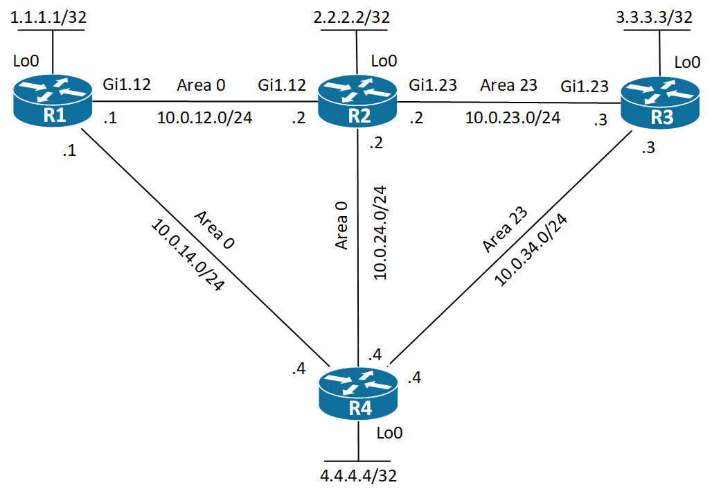
As you can see, I’ve configured the link between the two ABRs in area 0 and the link between R4 and R3 in area 23 – the stub area. Also I’ve added a link between R1 and R4 for redundancy purposes.
R2 is still configured for the totally stubby function making it inject just one Type 3 LSA which is the default route. R4 also injects the default route, but will also flood Type 3 LSAs for all inter-area prefixes. This configuration serves two purposes:
- Adds redundancy by having two ABRs (R2 and R4)
- Provides load sharing of traffic exiting area 23.
The first purpose if obvious. Two routers providing reachability to area 23 gives us redundancy. If one ABR goes down, we can still use the other. The next benefit of this design is that when R3 wants to send traffic to destinations internal to our OSPF domain, we’ll transit R4, because routers use the longest match routing decision.
What about the default route then? In this topology, because we’ve two Gigabit links between R3 and the ABRs, R3 will actually do ECMP for the default route. We can change this, though by changing the cost of the default route generated by R4, making all external traffic go through R2 and all internal traffic go through R4, still providing redundancy. Let’s see how we go about this on R4. First I’ll show that R3 is in fact doing ECMP:
! R3 verification of ECMP:

R3#sh ip route ospf | be Gateway
Gateway of last resort is 10.0.34.4 to network 0.0.0.0

O*IA 0.0.0.0/0 [110/2] via 10.0.34.4, 00:00:47, GigabitEthernet1.34
               [110/2] via 10.0.23.2, 00:40:46, GigabitEthernet1.23
     10.0.0.0/8 is variably subnetted, 7 subnets, 2 masks
O IA   10.0.12.0/24 [110/3] via 10.0.34.4, 00:24:20, GigabitEthernet1.34
O IA   10.0.14.0/24 [110/2] via 10.0.34.4, 00:00:09, GigabitEthernet1.34
O IA   10.0.24.0/24 [110/2] via 10.0.34.4, 00:24:20, GigabitEthernet1.34
R3#
! R4 change cost of default route:
R4(config)#router ospf 1
R4(config-router)#area 23 default-cost 44
R4(config-router)#
We’ll verify on R3:
! R3 verification of default routing:

R3#sh ip route ospf | be Gateway
Gateway of last resort is 10.0.23.2 to network 0.0.0.0

O*IA 0.0.0.0/0 [110/2] via 10.0.23.2, 00:42:39, GigabitEthernet1.23
     10.0.0.0/8 is variably subnetted, 7 subnets, 2 masks
O IA    10.0.12.0/24 [110/3] via 10.0.34.4, 00:26:13, GigabitEthernet1.34
O IA    10.0.14.0/24 [110/2] via 10.0.34.4, 00:02:02, GigabitEthernet1.34
O IA    10.0.24.0/24 [110/2] via 10.0.34.4, 00:26:13, GigabitEthernet1.34
R3#

R3#sh ip ospf database summary 0.0.0.0

            OSPF Router with ID (3.3.3.3) (Process ID 1)

               Summary Net Link States (Area 23)

LS age: 640
Options: (No TOS-capability, DC, Upward)
LS Type: Summary Links(Network)
Link State ID: 0.0.0.0 (summary Network Number)
Advertising Router: 2.2.2.2
LS Seq Number: 80000005
Checksum: 0x6DC4
Length: 28
Network Mask: /0
MTID: 0 Metric: 1

LS age: 32
Options: (No TOS-capability, DC, Upward)
LS Type: Summary Links(Network)
Link State ID: 0.0.0.0 (summary Network Number)
Advertising Router: 4.4.4.4
LS Seq Number: 80000005
Checksum: 0xE01E
Length: 28
Network Mask: /0
MTID: 0 Metric: 44

R3#
Now we see that R3 is no longer using ECMP, but only uses one path for the default route (via R2). In the LSDB we see why. The Metric: 44 is set on the 0.0.0.0 Summary LSA from R4 making it less desirable.
What we’ve essentially done now is configured traffic engineering for area 23.
NSSA
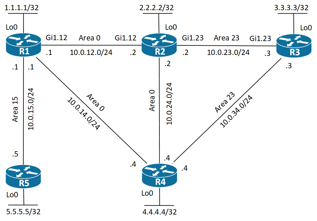
Not So Stubby Area (NSSA) is the third area type. I’ll expand the topology again adding R5 to R1:
First I’ll show how you configure area 15 as NSSA:
! R5 NSSA Configruation:
R5(config)#router ospf 1
R5(config-router)#area 15 nssa
R5(config-router)#
That’s it! As simple as configuring the stub area. Let’s have a look at the Hello packet sent by R5:
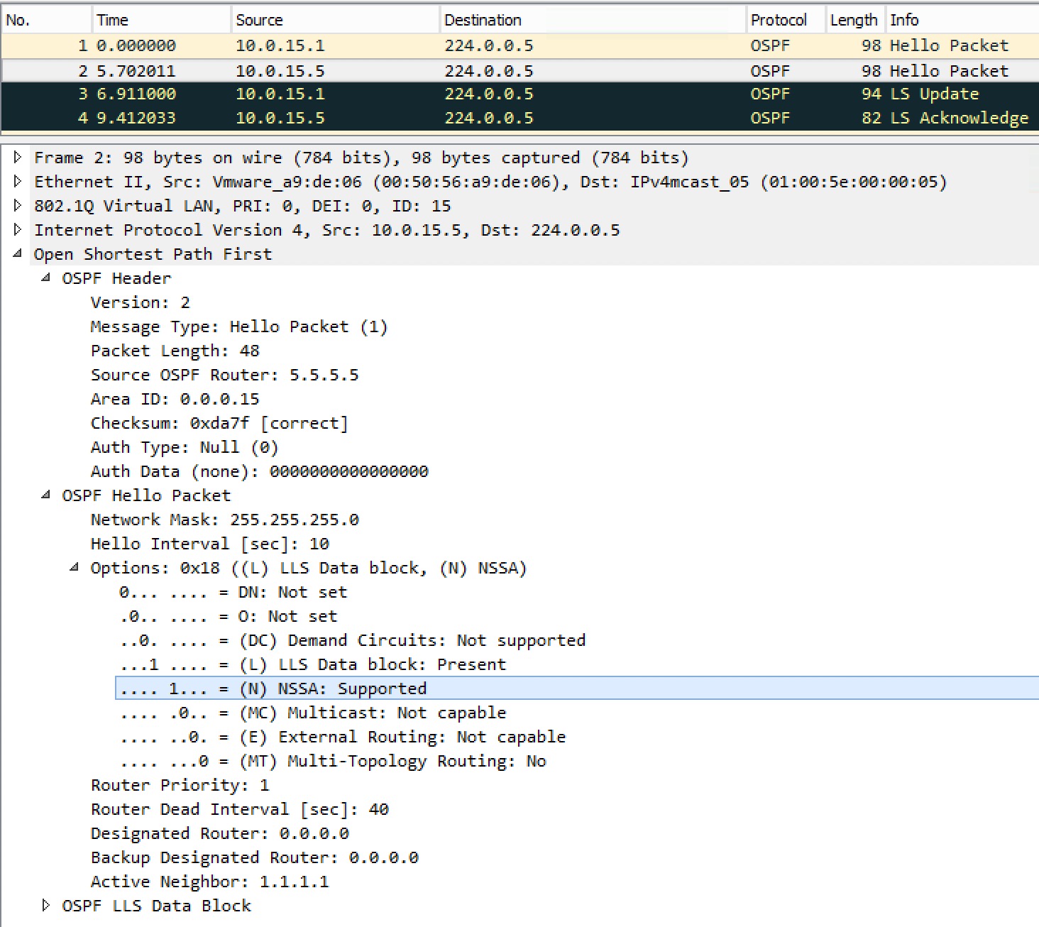
As expected we see a bit set for the NSSA feature. Also notice that we’re still not allowing External Routing leaving the E bit unset (0), because this is a type of stub area!
Remember I did a redistribution of Lo0 on R1? Let’s see how this looks like on R5:
! R5 Routing Table:

R5#sh ip route ospf | be Gateway
Gateway of last resort is not set

1.0.0.0/32 is subnetted, 1 subnets
O N2  1.1.1.1 [110/20] via 10.0.15.1, 00:16:33, GigabitEthernet1.15
      10.0.0.0/8 is variably subnetted, 7 subnets, 2 masks
O IA     10.0.12.0/24 [110/2] via 10.0.15.1, 00:16:33, GigabitEthernet1.15
O IA     10.0.14.0/24 [110/2] via 10.0.15.1, 00:16:33, GigabitEthernet1.15
O IA     10.0.23.0/24 [110/3] via 10.0.15.1, 00:16:33, GigabitEthernet1.15
O IA     10.0.24.0/24 [110/3] via 10.0.15.1, 00:16:33, GigabitEthernet1.15
O IA     10.0.34.0/24 [110/3] via 10.0.15.1, 00:16:33, GigabitEthernet1.15
R5#
We see it as an O N2 route (NSSA External Type 2). The reason is that although we’re not allowed to flood external route information into a stub area – be it stub or nssa – we are still allowed to redistribute other routing domains (or just connected interfaces) into a NSSA. The trick is that OSPF uses a LSA Type 7 (nssa-external). I’ve actually also redistributed R5’s Lo0 into the NSSA, too.
On R1 which is now an ABR, you might now want the connected routes to be originated into the NSSA. You can stop this default behavior by not allowing redistribution into the NSSA at all:
! R1 no redistribution into NSSA:
R1(config)#router ospf 1
R1(config-router)#area 15 nssa no-redistribution
R1(config-router)#
Let’s verify on R5:
! R5 verify R1's Lo0 is gone:

R5#sh ip route ospf | be Gateway
Gateway of last resort is not set

      10.0.0.0/8 is variably subnetted, 7 subnets, 2 masks
O IA     10.0.12.0/24 [110/2] via 10.0.15.1, 00:23:04, GigabitEthernet1.15
O IA     10.0.14.0/24 [110/2] via 10.0.15.1, 00:23:04, GigabitEthernet1.15
O IA     10.0.23.0/24 [110/3] via 10.0.15.1, 00:23:04, GigabitEthernet1.15
O IA     10.0.24.0/24 [110/3] via 10.0.15.1, 00:23:04, GigabitEthernet1.15
O IA     10.0.34.0/24 [110/3] via 10.0.15.1, 00:23:04, GigabitEthernet1.15
R5#
Sure we only see the inter-area prefixes in the routing table. Notice that we do not have a inter-area default route as we did with the stub area! This is expected in a NSSA. I’ll show the options for doing this a bit later. And the LSDB?
! R5 LSDB of nssa-external:

R5#sh ip ospf database nssa-external

           OSPF Router with ID (5.5.5.5) (Process ID 1)

               Type-7 AS External Link States (Area 15)

 LS age: 1432
 Options: (No TOS-capability, Type 7/5 translation, DC, Upward)
 LS Type: AS External Link
 Link State ID: 5.5.5.5 (External Network Number )
 Advertising Router: 5.5.5.5
 LS Seq Number: 80000003
 Checksum: 0x4A04
 Length: 36
 Network Mask: /32
       Metric Type: 2 (Larger than any link state path)
       MTID: 0
       Metric: 20
       Forward Address: 10.0.15.5
       External Route Tag: 0

R5#
We only see the redistributed Lo0 of R5 – nothing from R1!
Say we’d like communication between R3’s Lo0 and R5’s Lo0. Right now, because the NSSA has no route to R3’s Lo0 prefix, 3.3.3.3/32, no communication is possible. R3 will have a route to R5’s prefix, because R1 being an ABR, will actually translate the Type 7 LSAs into Type 5 LSAs. This is because the Type 7 LSAs are are local LSAs, meaning they are not allowed to leave the NSSA.
So what is the options for establishing this communication request between R3 and R5? Like we did in the stub area, we can tell the ABR, R1, to generate a default route into the NSSA:
! R1 originate a default route into NSSA:
R1(config)#router ospf 1
R1(config-router)#area 15 nssa default-information-originate
R1(config-router)#
We’ll verify on R5:
! R5 Routing Table:

R5#sh ip route ospf | be Gateway
Gateway of last resort is 10.0.15.1 to network 0.0.0.0

O*N2 0.0.0.0/0 [110/1] via 10.0.15.1, 00:00:45, GigabitEthernet1.15
       10.0.0.0/8 is variably subnetted, 7 subnets, 2 masks
O IA     10.0.12.0/24 [110/2] via 10.0.15.1, 00:33:54, GigabitEthernet1.15
O IA     10.0.14.0/24 [110/2] via 10.0.15.1, 00:33:54, GigabitEthernet1.15
O IA     10.0.23.0/24 [110/3] via 10.0.15.1, 00:33:54, GigabitEthernet1.15
O IA     10.0.24.0/24 [110/3] via 10.0.15.1, 00:33:54, GigabitEthernet1.15
O IA     10.0.34.0/24 [110/3] via 10.0.15.1, 00:33:54, GigabitEthernet1.15
R5#
And we should have reachability now:
! R5 ping R3's Lo0:
R5#ping 3.3.3.3 so lo0
Type escape sequence to abort.
Sending 5, 100-byte ICMP Echos to 3.3.3.3, timeout is 2 seconds:
Packet sent with a source address of 5.5.5.5
!!!!!
Success rate is 100 percent (5/5), round-trip min/avg/max = 5/6/7 ms
R5#
Success! But what about all of those inter-area routes? We don’t really need them as we currently only have one exit point out of area 15. Can we optimize? Yes! Let’s do that…
! R1 Stop flooding LSA Type 3 into NSSA:
R1(config)#router ospf 1
R1(config-router)#area 15 nssa no-summary
R1(config-router)#no area 15 nssa default-information-originate
R1(config-router)#
First we do what we did for the totally stubby area function, which is configure the keyword no-summary on the ABR, R1 in this case. But we still originate a default LSA Type 7 prefix, so I remove that as we have no need for it now. Verification time:
! R5 Routing Table:


R5#sh ip route ospf | be Gateway
Gateway of last resort is 10.0.15.1 to network 0.0.0.0

O*IA 0.0.0.0/0 [110/2] via 10.0.15.1, 00:01:45, GigabitEthernet1.15
R5#
What a nice table!
Using NSSA with the LSA Type 7 default route is referred to as NSSA Stub. And the NSSA with the LSA Type 3 default route (filtering all other LSA Type 3) is called Totally NSSA.
Forward Address
The forward address of Type 5 and Type 7 LSAs is used to provide optimal routing to external prefixes.
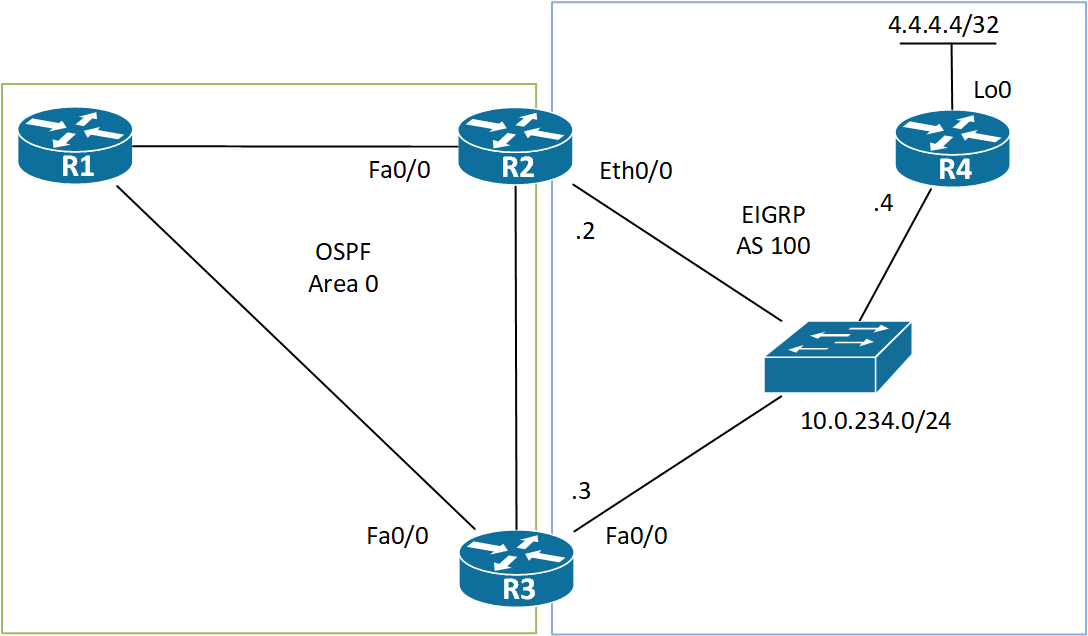
If we look at the above topology, we see that R2 and R3 connect to the outside domain – EIGRP. R2 has a 10Mbps link and R3 has a 100Mbps link. How will R1 decide which path to take when it needs to send traffic to R4’s Lo0? As a human its obvious that R3 is the better path due to its higher link speed. But OSPF must somehow have insight in these costs. This is where the FA (Forward Address) comes in! It is also the reason why you must have an OSPF route to the FA! – either intra-area or inter-area. In order to be able to set the FA on Type 5 LSAs, the following must be true on the ASBRs:
- OSPF is enabled on the ASBR’s next hop interface, AND
- The interface is non-passive, AND
- The interface has a DR network type, meaning broadcast or non-broadcast
If all of these criteria are present, the ASBR can set the FA to the next hop IP address of the route. This means that the FA in this case will be set to 10.0.234.4. Back to the cost issue of this next hop. Because we have enabled OSPF on R2’s Eth0/0 and R3’s Fa0/0 link, R1 knows the cost of both ASBR’s links towards the next hop and is able to use this cost in its FM (Forward Metric).
To avoid redundant information, just one of the ASBRs will originate the Type 5 LSA for the external prefix. This is why the interfaces must not be passive – we need an adjacency to be able to tell which router should generate the external LSAs. The router with the highest RID wins and generates the Type 5 LSAs – R3 in this case. Enough theory, let’s jump to the CLI and have a look under the hood. We’ll start by looking at the path R1 chooses to reach 4.4.4.4/32. Please note that I am demonstrating this inside “VRF a”, but the same theory applies regardless of VRFs.
! R1 Route to 4.4.4.4/32:

R1# sh ip route vrf a 4.4.4.4

Routing Table: a
Routing entry for 4.4.4.4/32
  Known via "ospf 10", distance 110, metric 20, type extern 2, forward metric 2
  Last update from 10.0.31.3 on GigabitEthernet1.31, 00:03:17 ago
  Routing Descriptor Blocks:
  * 10.0.31.3, from 0.0.0.3, 00:03:17 ago, via GigabitEthernet1.31
      Route metric is 20, traffic share count is 1
R1#
We’re using R3 as the next hop and our FM is 2! Excellent! Let’s see what’s in the LSDB:
! R1 LSDB of Type 5 LSA:

R1#sh ip ospf 10 database external

            OSPF Router with ID (0.0.0.1) (Process ID 10)

                Type-5 AS External Link States

 LS age: 1148
 Options: (No TOS-capability, DC, Upward)
 LS Type: AS External Link
 Link State ID: 4.4.4.4 (External Network Number )
 Advertising Router: 0.0.0.3
 LS Seq Number: 80000001
 Checksum: 0xB1E2
 Length: 36
 Network Mask: /32
       Metric Type: 2 (Larger than any link state path)
       MTID: 0
       Metric: 20
       Forward Address: 10.0.234.4
       External Route Tag: 0

R1#
Just the one LSA originated by R3! Just as predicted and dictated by the theory. Note the FA is set to 10.0.234.4 as we also expected.
If we somehow filter 10.0.234.0/24 from being advertised into Area 0, R1 will not be able to install the route to 4.4.4.4/32. It will still have it in its LSDB, though, but with no intra-area or inter-area route to the FA, the router cannot calculate the FM which invalidates the external routing information and the prefix is removed from the routing table. This is also true if you somehow learned the FA as an OSPF external route.
Virtual Link
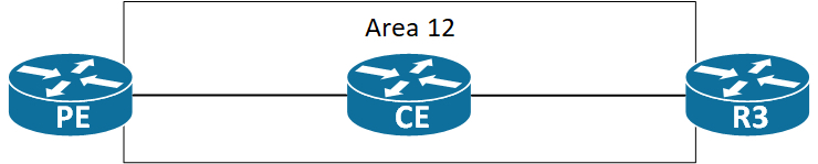
OSPF requires a strict two level hierarchy where every area must connect to area 0, the backbone area. If either area 0 gets partitioned, or somehow an area is attached behind a non-backbone area, this requirement of two levels is broken. To repair the issue, you can use a VL (virtual link). What is the function of a VL? It allows the router that has an area behind the non-backbone area to have an interface in area 0 thereby restoring the requirement of two levels.
If we look at this OSPF network, we quickly see that something is wrong. The area design is invalid, because area 34 is not connected to area 0. The problem is that R3 borders between area 23 and area 34. In OSPF an ABR is a router that connects to area 0 and a non-backbone area. R3 lacks this requirement of connecting to area 0. We can fix this by creating a VL between R2 and R3.
To see the problem, we can look at the routing table of R2. It should not have a route to 4.4.4.4/32, but R3 does.
! R2 before VL creation:
R2#sh ip route 4.4.4.4
% Network not in table
R2#
Looking at R4 it should have an intra-area route to 4.4.4.4/32.
! R3 before VL creation:
R3#sh ip route 4.4.4.4
Routing entry for 4.4.4.4/32
  Known via "ospf 1", distance 110, metric 2, type intra area
  Last update from 10.0.34.4 on GigabitEthernet1.34, 00:00:00 ago
  Routing Descriptor Blocks:
  * 10.0.34.4, from 4.4.4.4, 00:00:00 ago, via GigabitEthernet1.34
     Route metric is 2, traffic share count is 1
R3#
Before we dive into the configuration of the VL, let’s see what the characteristics of a VL:
- Unicast adjacency in Area 0
- Point-to-point network type
- Runs as On-Demand Circuit
- Hellos suppressed
You might think that with a unicast P2P adjacency a neighbor configuration is needed. This is not the case. If this was true, which IP address should you then use? And if that link goes down? OSPF has no concept of an update-source like BGP does. The best thing is to let OSPF figure it our by itself. Because the two routers are in the same area (they must be), they’ll know about the other routers Type 1 LSA. In here they find a stub network that they can use as the destination. This is what the routers will use to reach each other. Now let’s have a look at the config.
! R3 Virtual Link Configuration:
R3(config)#router ospf 1
R3(config-router)#area 12 virtual-link 2.2.2.2
R3(config-router)#
So to establish this area 0 adjacency with R2 (2.2.2.2), look for the Type 1 LSA in area 12. On R2 the configuration is identical, but uses the router-id of R3 (3.3.3.3).
We can verify the adjacency:
! R3 VL verification:
R3#sh ip ospf virtual-link
Virtual Link OSPF_VL1 to router 2.2.2.2 is up
Run as demand circuit
DoNotAge LSA allowed.
Transit area 12, via interface Ethernet0/0
Topology-MTID Cost Disabled Shutdown Topology Name
0 10 no no Base
Transmit Delay is 1 sec, State POINT_TO_POINT,
Timer intervals configured, Hello 10, Dead 40, Wait 40, Retransmit 5
Hello due in 00:00:02
Adjacency State FULL (Hello suppressed)
Index 1/1, retransmission queue length 0, number of retransmission 0
First 0x0(0)/0x0(0) Next 0x0(0)/0x0(0)
Last retransmission scan length is 0, maximum is 0
Last retransmission scan time is 0 msec, maximum is 0 msec
R3#
We can also look at a capture of the establishment of the adjacency:
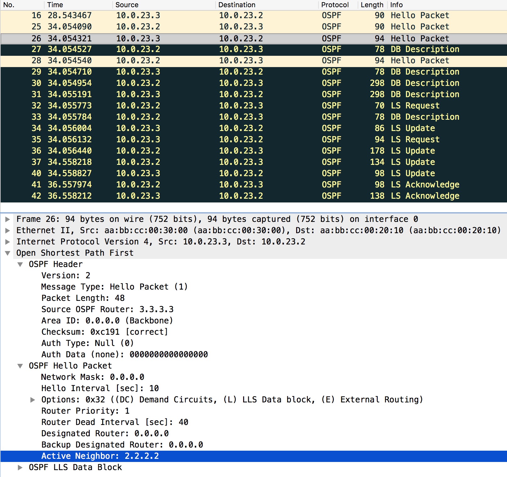
First of all we see the usual Hello packets letting the routers present themselves to each other. Next they verify that they have seen each other by listing the Active Neighbor in the Hello packet. They both do that. Now the sync of the LSDB can happen and the adjacency is eventually FULL.
Now that the VL is up and we have an adjacency over it, let’s see the routing table on R2 again:
! R2 after VL:
R2#sh ip route 4.4.4.4
Routing entry for 4.4.4.4/32
  Known via "ospf 1", distance 110, metric 3, type inter area
  Last update from 10.0.23.3 on GigabitEthernet1.23, 00:00:00 ago
  Routing Descriptor Blocks:
  * 10.0.23.3, from 3.3.3.3, 00:00:00 ago, via GigabitEthernet1.23
      Route metric is 3, traffic share count is 1
R2#
Now we see an inter-area route to 4.4.4.4/32, because R3 now can act as an ABR having an interface in area 0 and another in a non-backbone area (34 in this case).
Sham Link
Below is a simple topology to go through what a sham link is and why you might want to use it.
Let’s say that the customer above has a backdoor link between R3 and R4. Perhaps the customer decided to buy a cheap connection for redundancy purposes. Whatever the reason, if this backdoor link is a very slow speed link that the customer only wants to utilize when the link to one of the PE routers goes down, we might have to help with correcting the routing issues for the customer.
Routing issues? Take a look at the topology. The customer runs OSPF in area 0 between his routers. OSPF always prefers intra-area routes over inter-area router. And Inter-area routers are preferred over external routes. In this case the prefixes are learned as intra-area, because the customer does not do multi-area OSPF. So far so good – or bad. It turns out that when you run OSPF as a PE-CE routing protocol, the best you can do with the default behavior is sending inter-area prefixes to the customer. Why inter-area? Because the MPLS backbone of the SP acts as a superbackbone area to OSPF, meaning a level higher than area 0. This actually causes the PE routers to become ABRs and they will generate Type 3 LSAs for the prefixes redistributed from BGP into OSPF. There is a catch. The PE routers will only generate Type 3 LSAs if the Domain ID of the BGP prefix matches with the OSPF process for the customer. If the OSPF process ID differs between the two PE routers, they will generate Type 5 LSAs instead! This means that the customer will use its bad link between R3 and R4, because O is better than O IA. But we can help the customer. The tool we need is called a sham link. Let’s have a look at it.
A bit like a virtual link, you can configure a sham link, which is a P2P unicast adjacency in area 0 between two PE routers running MPLS VPNs
To see the problem, let’s look at R3’s routing table for 4.4.4.4/32 (R4’s Lo0):
! R3 routing table:
R3#sh ip route 4.4.4.4
Routing entry for 4.4.4.4/32
  Known via "ospf 1", distance 110, metric 101, type intra area
  Last update from 10.0.34.4 on GigabitEthernet1.34, 00:00:06 ago
  Routing Descriptor Blocks:
   * 10.0.34.4, from 10.0.24.4, 00:00:06 ago, via GigabitEthernet1.34
       Route metric is 101, traffic share count is 1
R3#
So R3 is using the link to R4 to reach R4’s Lo0. This is not what the customer wanted. Let’s have a look at the sham link that will solve the problem.
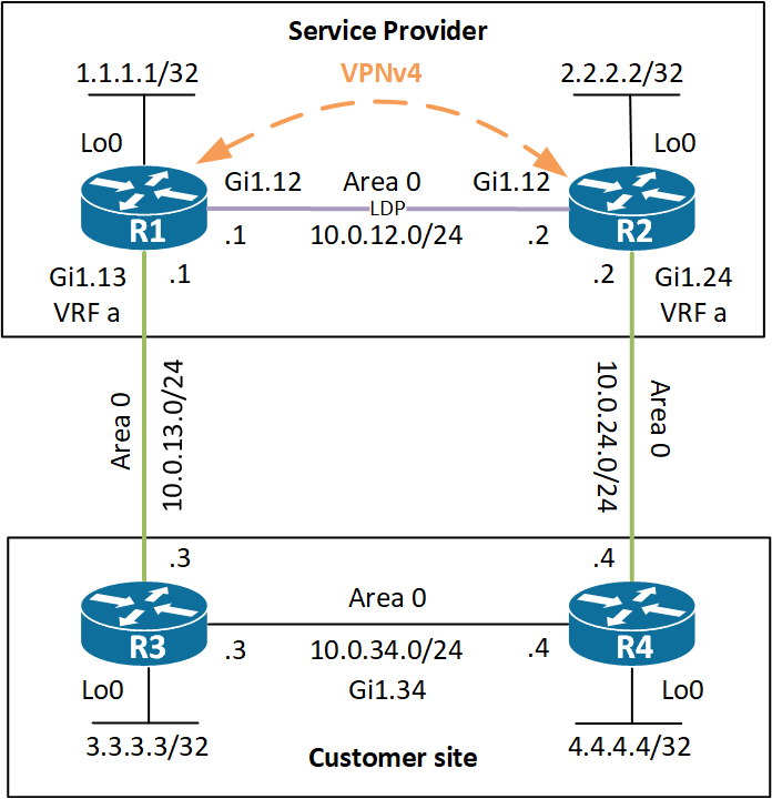
Focusing on the OSPF part of the above topology, let’s have a look at the configuration of one of the PEs.
! R1 sham link configuration:
interface Loopback10
 vrf forwarding a
 ip address 10.10.10.1 255.255.255.255
!
router bgp 12
!
 address-family ipv4 vrf a
  network 10.10.10.1 mask 255.255.255.255
  redistribute ospf 10
 exit-address-family
!
router ospf 10 vrf a
 area 0 sham-link 10.10.10.1 10.10.10.2
The first thing that must be done is creating a new interface in the customer VRF. This will be used as the unicast source and destination of the sham link. You must� not� advertise this into OSPF – only into BGP!
Next the sham link is configured in area 0 and you’re done. Verification is next.
! R1 sham link verification
R1#sh ip ospf 10 sham-links
Sham Link OSPF_SL2 to address 10.10.10.2 is up
Area 0 source address 10.10.10.1
  Run as demand circuit
  DoNotAge LSA allowed. Cost of using 1 State POINT_TO_POINT,
  Timer intervals configured, Hello 10, Dead 40, Wait 40,
    Hello due in 00:00:03
    Adjacency State FULL (Hello suppressed)
    Index 2/2, retransmission queue length 0, number of retransmission 0
    First 0x0(0)/0x0(0) Next 0x0(0)/0x0(0)
    Last retransmission scan length is 0, maximum is 0
    Last retransmission scan time is 0 msec, maximum is 0 msec
R1#
R1#sh ip ospf 10 neighbor

Neighbor ID   Pri   State       Dead Time     Address      Interface
10.0.24.2.      0   FULL/ -        -          10.10.10.2   OSPF_SL2
10.0.13.3       1   FULL/DR     00:00:31      10.0.13.3    GigabitEthernet1.13
R1#
And if we now look at which way R3 will go to reach R4’s Lo0:
! R3 routing table:
R3#sh ip route 4.4.4.4
Routing entry for 4.4.4.4/32
  Known via "ospf 1", distance 110, metric 4, type intra area
  Last update from 10.0.13.1 on GigabitEthernet1.13, 00:07:02 ago
  Routing Descriptor Blocks:
   * 10.0.13.1, from 10.0.24.4, 00:07:02 ago, via GigabitEthernet1.13
       Route metric is 4, traffic share count is 1
R3#
It’s using R1 as the next hop. Problem solved! Note that this was only solved, because of the metric of the route to reach 4.4.4.4/32. Given that the link the customer bought between R3 and R4 was a slow link, the cost should be higher. So either the customer changed the bandwidth configuration of the interface, or configured an OSPF cost on the interface. Both should be done. In the above the metric before the sham link was configured was 101. After the sham link had been configured the cost is now 4 (the default cost of a sham link is 1).
Domain Tag
Here we’re using OSPF as a PE-CE routing protocol. The domain tag is used and set by the PE routers to prevent loops for Type 5 and Type 7 LSAs, because these LSAs are the only ones capable of carrying a tag. It is set upon redistributing between MP-BGP and OSPF. The domain tag is a 32-bit number where the least significant 16 bits represents the ASN of the PE. � Note the PE router will only generate external LSAs when the OSPF Domain ID does not match in the VPNv4 prefix. The Domain ID is the OSPF process ID carried as an extended community in the VPNv4 update.
If we imagine the same topology as I used when explaining sham links� and we do not filter the Lo10 on R1 which has an IP address of 10.10.10.1/32. Now this gets redistributed into OSPF as an external route. If we debug ospf spf on R2, we see this:
! R2 debug ospf 10 spf:
OSPF-10 EXTER: Start partial processing Type 5 External LSA 10.10.10.1, mask 255.255.255.255
OSPF-10 EXTER: adv_rtr 10.0.13.1, age 3600, seq 0x80000008, metric 16777215, metric-type 2, fw-addr 0.0.0.0
OSPF-10 EXTER: Tag equals to VPN Tag, ignoring the LSA
If we look at the LSDB:
! LSDB of External 10.10.10.1:
R2#sh ip ospf 10 database | in External|10.10.10.1|Tag
                Type-5 AS External Link States
Link ID       ADV Router    Age    Seq#          Checksum      Tag
10.10.10.1    10.0.13.1     414    0x80000009    0x00FE98      3489660940
10.10.10.1    10.0.24.2     411    0x80000005    0x002CE2      3489660940
R2#
Notice the Tag value of� 3489660940. In binary this is:
11010000 00000000 00000000 00001100
Since we’re using AS 12, we see that the 16 least significant bits (00000000 00001100) also equals 12. Therefore the tag equals our AS and the route must be looped (advertised by one of our other PEs).
Down Bit
OSPF uses the DN (Down) bit when a PE router advertises Type 3, 5, and 7 LSAs after redistribution of MP-BGP to OSPF. Like the Domain Tag� the DN bit is used as a loop prevention in OSPF and tells the PE router to not use this LSA in the OSPF route calculation. So the PE router will essentially ignore any LSA that has the DN bit set thereby not redistributing the prefix back into MP-BGP causing a loop.
Let’s see how you can tell whether the DN bit has been set:
! R3 LSDB:

R3#sh ip ospf database summary 5.5.5.5

            OSPF Router with ID (10.0.13.3) (Process ID 1)

                Summary Net Link States (Area 0)

  LS age: 574
  Options: (No TOS-capability, DC, Downward)
  LS Type: Summary Links(Network)
  Link State ID: 5.5.5.5 (summary Network Number)
  Advertising Router: 10.0.13.1
  LS Seq Number: 80000001
  Checksum: 0x6926
  Length: 28
  Network Mask: /32
        MTID: 0 Metric: 1

  LS age: 102
  Options: (No TOS-capability, DC, Downward)
  LS Type: Summary Links(Network)
  Link State ID: 5.5.5.5 (summary Network Number)
  Advertising Router: 10.0.24.2
  LS Seq Number: 80000002
  Checksum: 0x146E
  Length: 28
  Network Mask: /32
        MTID: 0 Metric: 1

R3#
The Downward option you see of each LSA is the DN bit. With this set, the LSA is ignored when running SPF.
A Cisco router running OSPF in a VRF-lite environment (like if the CE is running VRF-lite) will think it is connected to a MPLS VPN Superbackbone and check the DN bit. This causes the prefixes to not be installed in the routing table, because the router will not use the LSA for route calculation. You can tell it not to check for the DN bit by adding capability vrf-lite:
! R3 Configuration:
R3(config)#router ospf 1 vrf a
R3(config-router)#capability vrf-lite
R3(config-router)#
This tells R3 to ignore the DN bit when calculating routes, because now it knows it is not connected to a MPLS VPN Superbackbone.
Area Design
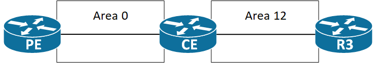
Using OSPF as a PE-CE routing protocol we have limited options for deciding on the areas we can use at a customer site. Let’s take a look at this design:

According to RFC 4477 Section 4.2.3� a PE router that has a link in a non-backbone area (like area 12 above) functions as an ABR. And since the OSPF backbone always contains all � ABRs, the PE is considered an area 0 router. This causes area 0 to be dis-contiguous in the topology above. The fix would be to create a VL (Virtual Link) between the PE and CE routers. Remember that a VL is always part of area 0! Another option exist. Whenever OSFP is run inside a VRF, the router automatically assumes it is part of the Super backbone which makes it an ABR and ASBR. We can disable this assumption by configuring the� capability vrf-lite� feature under the OSPF process of the PE router. I would not recommend this, though, because it disables setting the Down bit and the Domain Tag when originating LSAs to the CE – important loop prevention techniques.
Valid PE-CE OSPF area designs would be these:
You can run area 0 between the PE and CE. The PE will still consider itself as part of the Super backbone because OSPF is configured for a VRF. Now you have no problems with inter-area routes not being installed on the PE, because they are received in area 0, and according to RFC 2328 “Inter-area routes are not� summarized to the backbone. This is because inter-area routes are� always associated with the backbone area”. Remember the PE is an ABR connecting to the Super backbone – a level higher than area 0.
Here area 12 is stretched to� all� routers of the customer. This is a valid design. The PE acting as an ABR/ASBR can safely inject Type-3 LSAs into area 12.
In short we can conclude that a non-backbone router will use a Type-3 LSA� only if it is not an ABR itself. This also confirms the strict two level hierarchy of OSPF – or star formation of areas if you will (area 0 being the center of the star).
Prefix Suppression
Used to cut down on the size of the LSDB and routing table by filtering out transit links. It is enabled with just one command either at the process level or interface level.
When enabled it does not filter out:
- Loopback
- Secondary IP addresses
- Passive Interfaces
It does however filter out stub network (Type 3 link) information from the router LSA when this sub network also has a link to another router. And for the network LSA it sets the subnet mask to /32
You could see the prefix suppression as a security mechanism, because when enabled you do not attract traffic to the transit routers as you do not have reachability information for these.
Like I said it is a one line config:
router ospf 1
 prefix-suppression
or for interface specific config:
interface e0/0
 ip ospf prefix-suppression [disable]