Cisco PnP - Revisited
Table of Contents
I’ve gone over the Cisco PnP feature before. This time I will revisit the feature with focus on other areas. Specifically these cases will be discussed:
- PnP with Non-Vlan1 (conditionally)
- Re-use DHCP-assigned IP address on another interface
- PnP with an EtherChannel
PnP With Non-Vlan1 (Conditionally)
I briefly discussed this in my original post, but I ran in to a case where I actually wanted both a startup-vlan and the default of Vlan1.
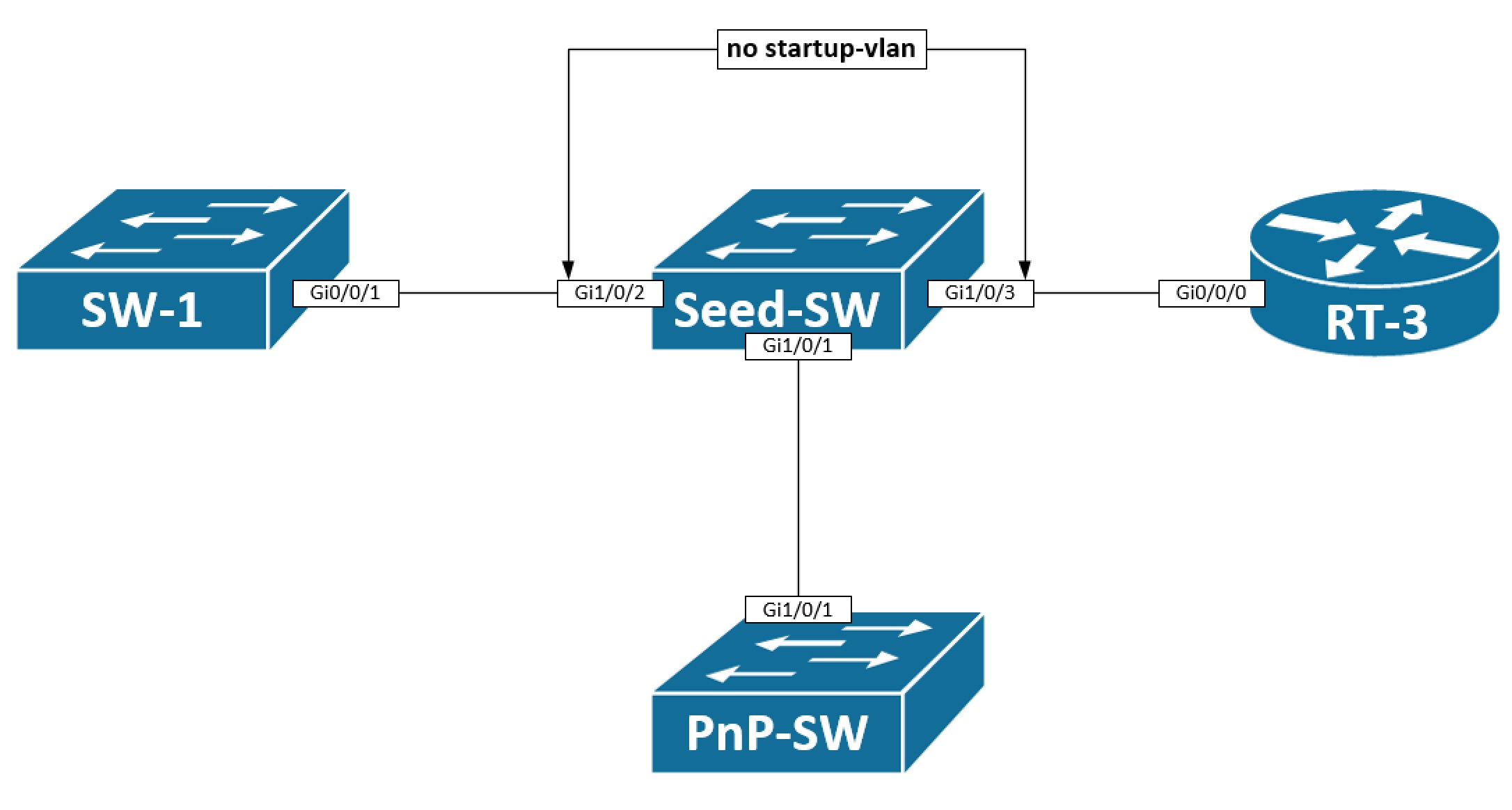
The idea is that my PnP-SW is a L2 switch that just requires a management IP address in the management vlan of the seed switch - in this case it could be Vlan9, for example. The other switches and routers to the left and right of the seed switch might also be provisioned using pnp, but here I use L3 routed ports on my seed switch making the startup-vlan 9 undesired on those links (Gi1/0/2 and Gi1/0/3).
The startup-vlan is propagated via a CDP Application TLV out all interfaces. If we look at what our seed switch sends out to the PnP-SW:
Seed_Switch#sh run | in pnp startup-vlan
pnp startup-vlan 9
Seed_Switch#
Seed_Switch#sh cdp nei | in ^PnP-Switch|Device
Device ID        Local Intrfce     Holdtme    Capability  Platform  Port ID
PnP-Switch       Gig 1/0/1         178              S I   C9300-24U Ten 1/0/1
Seed_Switch#
Seed_Switch#sh cdp tlv app gi1/0/1
APP TLV (Neighbor: PnP-Switch), Received tlv type: 4105,value: PID:C9300-24UX,VID:V01,SN:FCW2136L0DN
APP TLV (Gig 1/0/1), Configured tlv type: 4103, value: 9
APP TLV (Gig 1/0/1), Configured tlv type: 4105, value: PID:C9300-48U,VID:V01,SN:FCW2124L0F4

Seed_Switch#
Here we first verify that a startup-vlan has been configured. Next we find the interface where our PnP-SW is connected. Lastly, a look is taken at which CDP App TLVs are sent out this interface. Indeed we see that the tlv type 4103 defines a value 9 which is how the startup-vlan is encoded inside the TLV.
To disable the propagation of this TLV out the other interfaces, we can simply disable CDP APP TLV entirely on the interface:
interface GigabitEthernet1/0/2
 description SW-1
 no cdp tlv app
Re-use IP Address on a Different Interface
Let’s say you either purposefully or coinsidentally try to use the DHCP-assigned IP address the PnP device receives on anoter interface. Take a look at the below topology:
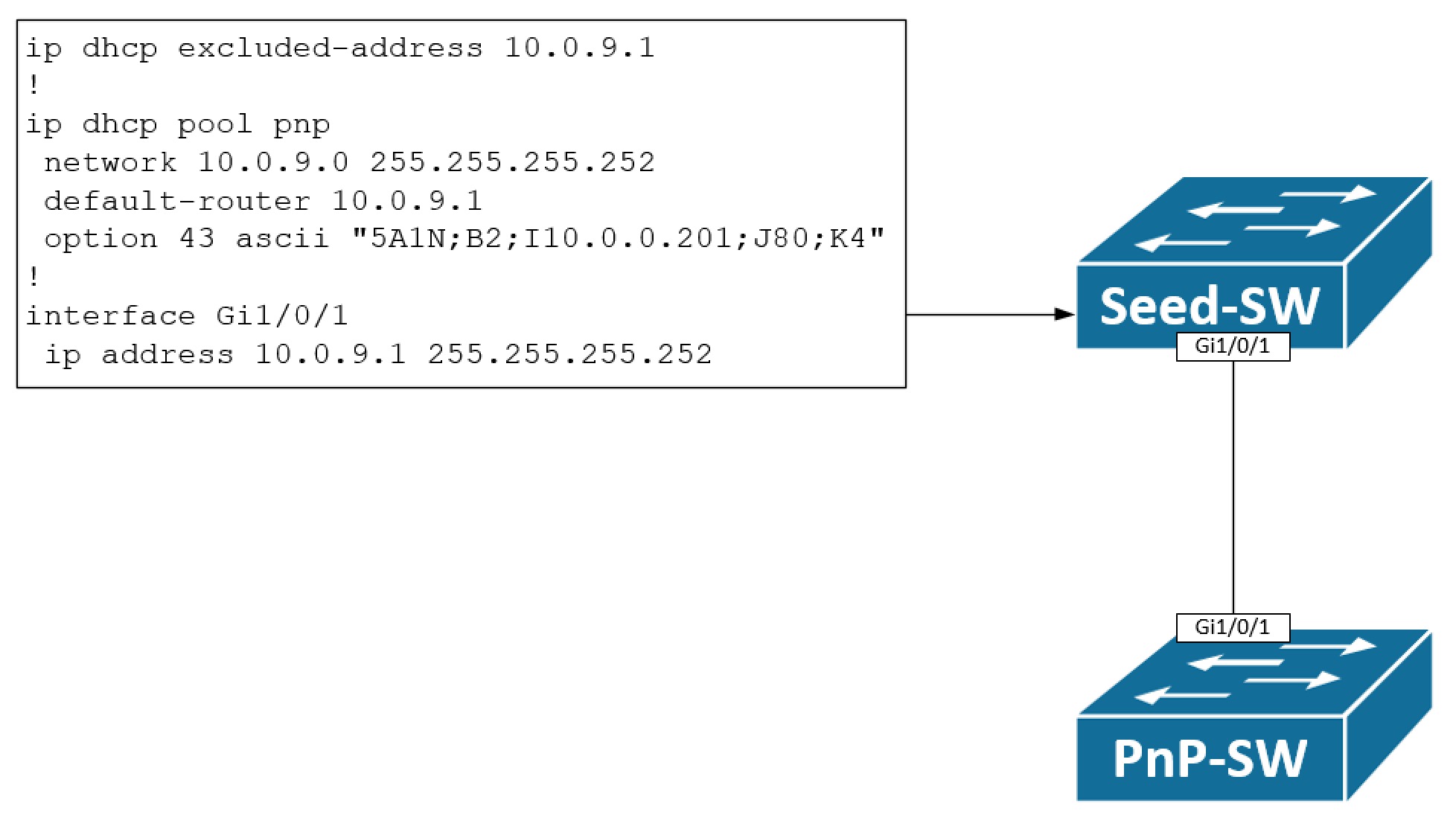
Here we have a simple topology with a seed switch and a pnp switch we want to provision. A DHCP pool has been configured on the seed switch allowing only for a single IP address to be leased - namely 10.0.9.2/30. The pnp switch will boot up and send out a DHCP Discover message on its Vlan1 interface, because this is the only available Layer 3 interface with no startup-config, unless of course you use the OoB Mgmt interface. It will assign the IP address 10.0.9.2/30 to Vlan1. The pnp switch might be used in a routed access solution or maybe we’re just building an underlay network for a new SD-Access implementation. Whatever the case is, the objective is to take the Vlan1 IP address and configure it under Gi1/0/1. Obviously, configuring 10.0.9.2/30 on Gi1/0/1 while the IP is also used on Vlan1 will generate an error of conflicting IP addresses - at least if Gi1/0/1 resides in the same routing table (GRT) as Vlan1 which is the case here. The somewhat easy solution to this problem is to un-configure Vlan1 before configuring the IP address on our routed Gi1/0/1 interface. The configuration template will look like this:
default interface vlan1
!
interface vlan1
 shutdown
!
ip routing
!
interface gi1/0/1
 no switchport
 ip address 10.0.9.2 255.255.255.252
 no shutdown
!
ip route 0.0.0.0 0.0.0.0 10.0.9.1
PnP With an EtherChannel
When deploying access switches EtherChannels could be involved. How does a pnp switch react to this when the seed device has an EtherChannel configured? You would think this causes problems with suspended links, but when configured correctly and using new switches/software, it will actually work almost with no extra configuration. Let’s have a look:
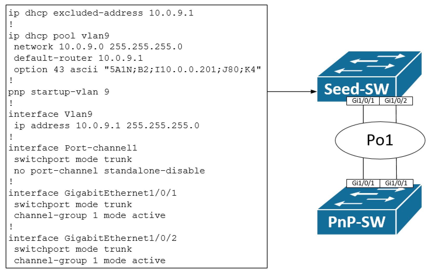
Here a regular LACP-based EtherChannel has been configured on our seed switch. The only added configuration is that we turn off the standalone disable feature, meaning that the switch will allow traffic coming in on a single link thereby not disabling/suspending it. It is needed to allow for the pnp switch to bring up a link towards the seed switch. When a link between the switches comes up, the pnp switch will detect (IOS XE 16.5.1 and later) if an EtherChannel is configured on the seed switch. When found, it will create an EtherChannel with one port active (the nummerically highest port id) and bundled (P) which allows for Layer 2 traffic to be forwarded.
The configuration template needed on the pnp switch is this:
int po1
 switchport mode trunk
 switchport trunk allowed vlan all
 no switchport access vlan 9
 no port-channel standalone-disable
!
int rang Gi1/0/1 , Gi1/0/2
 no description
 switchport mode trunk
 switchport trunk allowed vlan all
 no switchport access vlan 9
 channel-group 1 mode active
This configuration might seem odd with meaningless configuration. In particular these lines are of interest:
 no description
 switchport trunk allowed vlan all
 no switchport access vlan 9
Let me try to justify why this is needed with a practical example… I have some Catalyst 9300 switches in a lab. One, my pnp switch, has two TenGig interfaces connected to my seed switch which is already configured with an EtherChannel. The configuration template I’m pushing is this:
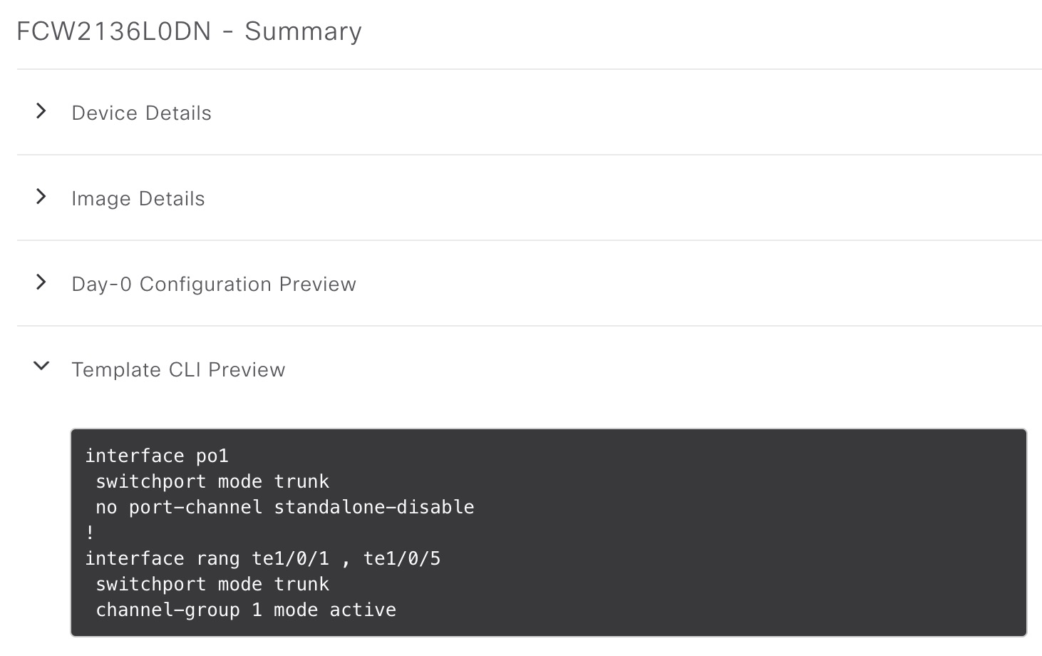
Once provisioned, the end result of the configuration is this:
interface Port-channel1
 switchport access vlan 9
 switchport trunk allowed vlan 9
 switchport mode trunk
 no port-channel standalone-disable
!
interface TenGigabitEthernet1/0/1
 switchport mode trunk
 channel-group 1 mode active
!
interface TenGigabitEthernet1/0/5
 description PNP STARTUP VLAN
 switchport access vlan 9
 switchport trunk allowed vlan 9
 switchport mode trunk
 channel-group 1 mode active
!
!
!
Switch#sh etherch sum | be ^Group
Group  Port-channel  Protocol    Ports
------+-------------+-----------+-----------------------------------------------
1      Po1(SU)         LACP        Te1/0/1(s)    Te1/0/5(P)

Switch#
If you do not configure the EtherChannel in a configuration template, you’ll end up with a similar situation with a one-legged EtherChannel and a regular trunk interface like this:
Switch#sh int trunk

Port        Mode             Encapsulation  Status        Native vlan
Gi1/0/1     auto             802.1q         trunking      1
Po1         on               802.1q         trunking      1

Port        Vlans allowed on trunk
Gi1/0/1     1-4094
Po1         9

Port        Vlans allowed and active in management domain
Gi1/0/1     1,9
Po1         9

Port        Vlans in spanning tree forwarding state and not pruned
Gi1/0/1     1,9
Po1         none
Switch#
Switch#sh span vlan 9

VLAN0009
  Spanning tree enabled protocol rstp
  Root ID    Priority    32777
             Address     2cab.eb4f.4980
             Cost        4
             Port        1 (GigabitEthernet1/0/1)
             Hello Time   2 sec  Max Age 20 sec  Forward Delay 15 sec

  Bridge ID  Priority    32777  (priority 32768 sys-id-ext 9)
             Address     f87b.2067.6780
             Hello Time   2 sec  Max Age 20 sec  Forward Delay 15 sec
             Aging Time  300 sec

Interface           Role Sts Cost      Prio.Nbr Type
------------------- ---- --- --------- -------- --------------------------------
Gi1/0/1             Root FWD 4         128.1    P2p
Po1                 Altn BLK 4         128.3049 P2p


Switch#
This wasn’t our intent! So, to successfully configure an EtherChannel you must clean up what pnp configures on the interfaces like I showed to begin with.
Conclusion
In this post we looked at various scenarios and use cases with PnP. First of I showed how you selectively can disable the advertisement of the CDP APP TLV out an interface. This is needed when you have a startup-vlan configured and do not want this to be propgated out specific ports.
Next, the objective was to re-use the DHCP-assigned IP address on another interface which is doable, but you need to de-configure the pnp-Vlan1 SVI first.
Lastly, PnP with an EtherChannel was discussed. This is also possible to configure. You must, however, do a bit of clean-up on the interfaces before the EtherChannel can be provisioned successfully.
I hope you enjoyed this post and found it useful.