Cisco PnP
Table of Contents
One of the main reasons to buy a DNA Center is to be able to harvest the benefits of automation. Many people associate DNAC with deploying an SD-Access network. SDA has a lot of focus these days and Cisco pushes hard to get it out there, but DNAC has many other uses cases besides SDA. SDA is actually just an application that you can install on a DNAC. It isn’t even installed by default when deploying a DNAC. This post will address a feature of DNAC that has been around for some time now. It used to be one of the main reasons why you’d use APIC-EM and now we’re lucky that it has been migrated and redesigned for DNAC. The feature is PnP (Plug’n Play). Let’s have a look at the benefits and workings of this awesome feature.
PnP Feature
PnP does the following for you with DNAC:
- Offers ZTD (Zero Touch Deployment) of Routers and Switches featuring:
- Image upgrade to a golden image for the device
- Template configuration
- Deploy network settings from DNAC
- Add device to inventory for a specified site
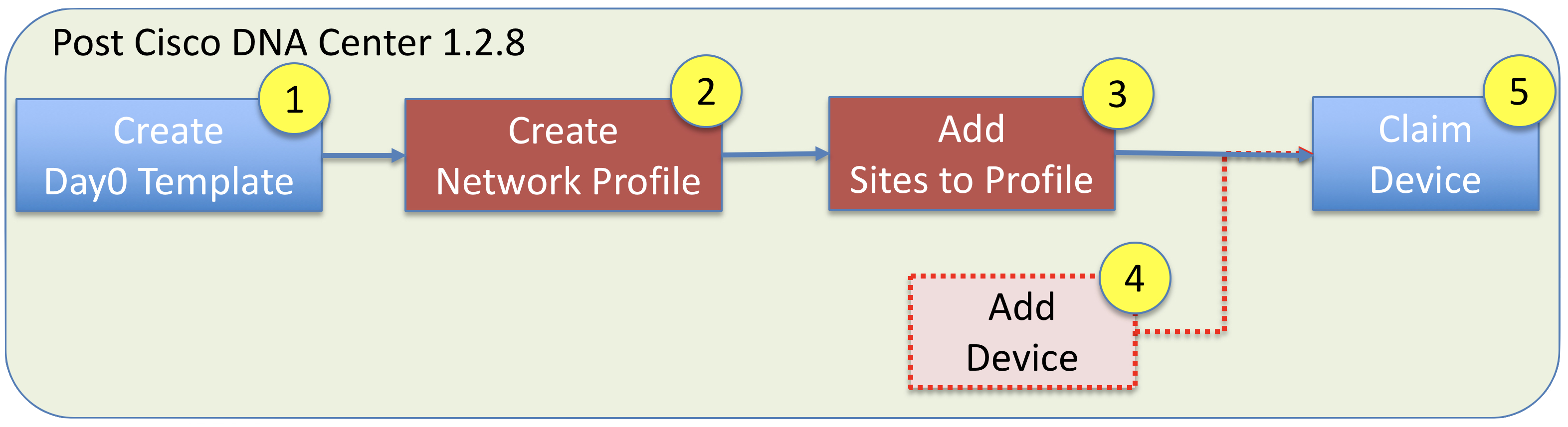
So the workflow for PnP with DNAC (post 1.2.8) is this:
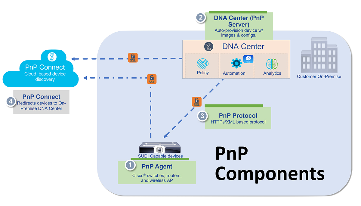
PnP Components
There are only a few components used to make PnP work.
PnP Prerequisites
Before you can start using PnP you must prepare your environment. There are a couple of ways to get the PnP agent to discover the PnP server (in order):
- DHCP
- DNS
- Plug and Play Connect
DHCP - uses option 43 to tell the PnP agent where and how to speak with the PnP server for initial contact.
DNS - this is the second option if DHCP fails. The device will try to lookup pnpserver.domain.tld where pnpserver should resolve to the IP address of your DNAC provided a domain name is handed out via DHCP and a DNS entry exists for pnpserver. Also the PnP agent will contact pnpntpserver.domain.tld for time synchronization.
Plug and Play Connect - is the third and last option. The PnP agent will try to contact devicehelper.cisco.com to obtain the IP address of DNAC.
I will only focus on the DHCP method as this is the first method used.
DHCP Configuration
In my lab I’m using an Ubuntu Linux server with the isc-dhcp-server package for DHCP services. It has this configuration in its /etc/dhcp/dhcpd.conf
option space CISCO_PNP;
option CISCO_PNP.pnpserver code 43 = string;

# PnP
subnet 100.64.64.0 netmask 255.255.255.240 {
  range 100.64.64.5 100.64.64.10;
  option routers 100.64.64.1;
  option domain-name "sda.domain.tld";
  option domain-name-servers 10.0.0.100;
}

class "ciscopnp" {
  match if option vendor-class-identifier = "ciscopnp";
  option vendor-class-identifier "ciscopnp";
  vendor-option-space CISCO_PNP;
  option CISCO_PNP.pnpserver "5A1N;B2;I10.0.0.201;J80;K4";
}
Option 43 Reference
| Option Code | Description |
|---|---|
| 5A1N | Specifies the DHCP suboption for Plug and Play, active operation, version 1, no debug information. It is not necessary to change this part of the string. |
| B2 | IPv4 address of DNAC. You could also use B1 which is the hostname of DNAC |
| I10.0.0.201 | This is the value for the “B”-setting above. In this case the IP address of DNAC as we specified B2 |
| J80 | Port number used to contact DNAC |
| K4 | Transport protocol. K4 is HTTP and K5 is HTTPS |
You must ensure that you have reachability between DNAC and this pool of addresses.
Avoid Vlan1
In case you want to avoid using Vlan1, but still have a trunk downstream, you can configure this on your upstream switch:
pnp startup vlan x
I’m using a routed port on my “core” switch and an IP helper pointing to my DHCP server at 10.0.0.100 (the Ubuntu box).
Step 1 - Create Day-0 Template
Once you have configured your environment for ZTD by PnP, it is time to start dealing with the configuration of DNAC. First step is to create a day-0 template using the Template Editor of DNAC.
Templates with DNAC uses the Velocity Template Language (VTL)
This gives you the ability to define variables in a template. By doing so, DNAC will ask for your input to fill out this variable when you claim a device for onboarding. You might want to use variables for configurations that need to be uniq to this device.
As of writing, DNAC only supports regular templates, not composite templates for PnP!
An example of a simple template using variables:
hostname $hostname
!
ip routing
!
interface loopback0
 ip address $lo0_ip 255.255.255.255
!
All commands are entered in conf t mode. As commands are delivered a prompt is expected after each command. This complicates thing if you want to enter multiple lines without a prompt being returned after each line of configuration. A banner would be an example of this. Also you might be asked questions when you configure things which also doesn’t show the regular prompt. Generating an SSH key pair could be an example of this. Sometimes you might need to enter stuff in exec mode.
Special keywords exist to address these challenges. Here is a list of them:
## ! Multiple Commands: **
<MLTCMD>First command
no prompt
still no prompt
last command</MLTCMD>
# now we have a prompt

## ! Interactive: **
#INTERACTIVE
crypto key generate rsa general-keys <IQ>yes/no<R> no
#ENDS_INTERACTIVE

## ! Exec mode commands: **
#MODE_ENABLE
<<commands>>
#MODE_END_ENABLE
Please note that they are case sensitive, they must be written in UPPER case! Also for MLTCMD you cannot start with a space and you must define the MLTCMD tags on separate lines! For more advanced use cases, please visit Adam Radfords blog series about PnP. Especially Using Velocity to create Plug and Play templates in DNA Center – Part 4
Do not forget to save and commit your newly defined template. If you neglect to do this, you’ll not be able to use it.
Step 2 - Network Profile
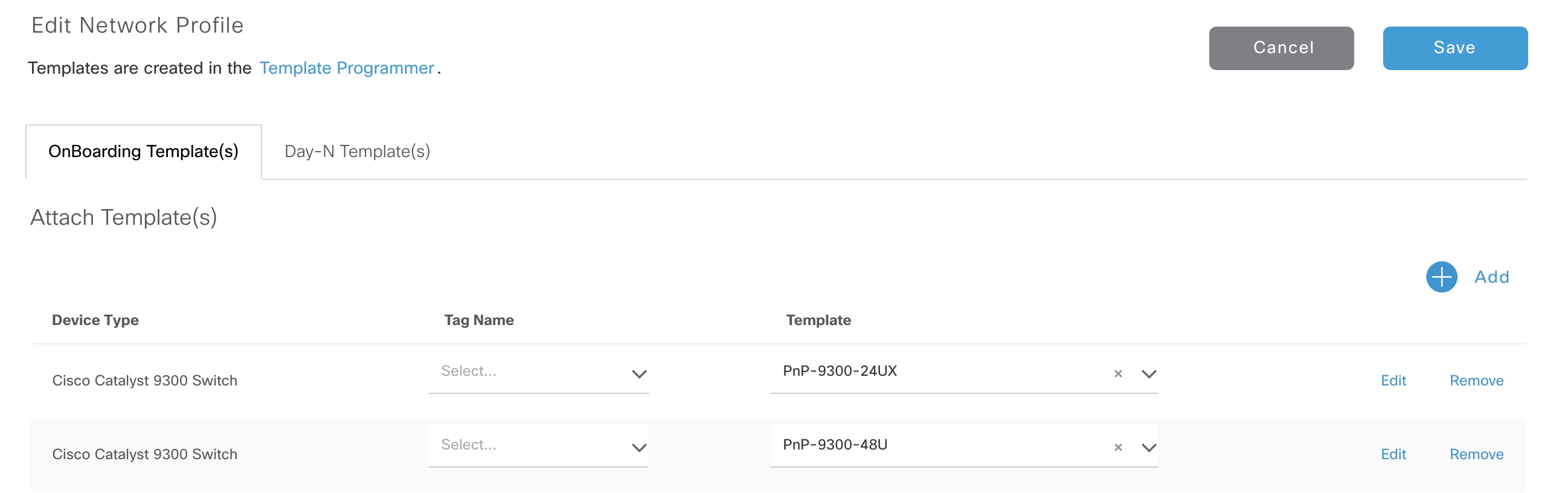
Once you’ve configured a new template, it must be assigned to a network profile. This can be configured in the Design section of DNAC. The PnP templates are added to the OnBoarding Template(s)
Here is an example of a network profile for switching:
Step 3 - Add Sites to Profile
You must specify the sites the network profile can be used by. This is done after you save the network profile. Sites are defined under the Network Hierarchy in the Design section of DNAC.
When you claim a device, you’ll be able to select between the templates you associated with this network profile.
Step 4 - Add Device
Now we’re getting there! In this step we can either add the device using its serial number ahead of it being cabled and powered on. This would be categorized as a “Planned” deployment. If you don’t do this, the device will show up under the Plug and Play menu of the Provision section of DNAC as “Initialized” - ready to be claimed.
Step 5 - Claim Device
The final step where we put it all together. Once you select a device and select “Claim”, a wizard will be shown. Here you select the site the device belongs to. Next you optionally define a golden image for this platform and a template. Then you enter the variables for the template which makes DNAC able to brew the final configuration using your input. The last and final page of the wizard presents you with an overview of the intent DNAC has for your device. If everything looks good, you can hit the “Claim” button and the device will be onboarded, configured, and added to the inventory of DNAC.
Note that once DNAC has completed the onboarding process and added the device to inventory, you can’t delete it from the “Plug and Play” menu. You must first delete it from Inventory
Other considerations
Some older documentation of PnP like the Solution Guide for Cisco Network Plug and Play says that during PnP the configuration is applied to the running configuration of the device. This instantly turns on my alarm bells in terms of cutting off the branch you’re sitting on. Meaning that if you change the IP address of an interface, make it a routed port instead of a switchport, or simply configure a VRF on it, you’ll immediately lose connectivity between the PnP server (DNAC) and the PnP agent (the device). Well, this is what you might think, but in reality PnP is actually capable of handling this potential issue. I haven’t been able to find any detailed documentation of how they do it, but it has to be something in line with this:
- Communication between the PnP agent and DNAC has been established and is working.
- The configuration template is delivered to the PnP agent and is stored in memory or in a temporary file in flash.
- After having received the complete configuration, the device says “Thank you. I might be gone for a bit now while reconfiguring myself. So long!”
- The device applies the configuration to the running config and, if successful, it will once again establish connectivity with DNAC letting it know that it went well.
- DNAC can now complete the onboarding process and add the device to the Inventory.
If you change routing or the interface from which the device communicates with DNAC (source interface for http), you can specify this line in the template:
ip http client source-interface <interface>
This will also make sure that DNAC new uses the IP address of this interface when adding it to the inventory. Now, how does DNAC know that this is the device returning to finalize the onboarding process once configuration has been changed and it now comes from a different IP address? My guess is that it always includes its serial number when communicating with DNAC.
Troubleshooting PnP
You don’t want a “Plug’n Pray” feel when dealing with PnP. If you should run in to problems, here are some of my learnings.
There is a way of specifying other stuff in DHCP option 43. This would be:
| Option Code | Description |
|---|---|
| Ttftp://10.0.0.100/ios.p7b | Optional parameter that specifies the external URL of the trustpool bundle if it is to be retrieved from a different location than the default, which is the Cisco DNA Center controller, which gets the bundle from the Cisco InfoSec cloud (http://www.cisco.com/security/pki/). |
| Zxxx.xxx.xxx.xxx | IP address of the NTP server. This parameter is mandatory when using trustpool security to ensure that all devices are synchronized. |
If you do this, but do NOT have reachability to the NTP server which is mandatory when specifying the trustpoolBundleURL, the device will never download the trustpool thereby not continuing the onboarding process. In DNAC you’ll see the OnBoarding State ** Connection Error** and on the device itself you see this:
Switch>sh pnp task

------------------ show pnp tasks ---------------------

Certificate-Install Task - Last Run ID:1, ST:7201, Result:Failed, LT:218276, ET:65358 ms
        Src:[http://pnpserver.domain.tld.:80/ca/pem], Dst:[pnplabel]
        Error Code:3341, Msg:[SSL Server ID check failed after cert-install]
When you fix the NTP access (routing/firewall) you’ll see this instead:
Loading ios.p7b from 10.0.0.100 (via Vlan1): !
[OK - 123493 bytes]

*Jun  1 08:40:37.650: %SMART_LIC-5-SYSTEM_CLOCK_CHANGED: Smart Agent for Licensing System clock has been changed
*Jun  1 08:40:38.061: %PKI-6-TRUSTPOOL_DOWNLOAD_SUCCESS: Trustpool Download is successful
*Jun  1 08:40:38.262: %PNP-6-HTTP_CONNECTING: PnP Discovery trying to connect to PnP server http://10.0.0.201:80/pnp/HELLO
*Jun  1 08:40:38.266: %PNP-6-HTTP_CONNECTED: PnP Discovery connected to PnP server http://10.0.0.201:80/pnp/HELLO
Jun  1 08:40:38.650: %PKI-6-AUTHORITATIVE_CLOCK: The system clock has been set.
Jun  1 08:40:39.271: %PNP-6-PROFILE_CONFIG: PnP Discovery profile pnp-zero-touch configured
Note the asterisk at the beginning of the log outputs. This tells that the timestamp is unreliable due to the device not being synchronized with NTP.
Now the PnP onboarding should continue and work correctly!
If the device couldn’t complete the onboarding process it will wait a while and then try to recover by rolling back all the commands given to it. To try again you have to reset the device state in DNAC first.
PnP Server Certificate
The PnP agent only looks in the SAN field of the certificate presented by DNAC. This means that DNAC’s IP address MUST be present in the SAN field of the cert. By default DNAC will put ALL IP addresses including the VIPs you specify during DNAC installation wizard in the self-signed cert. You can check the cert using this in your terminal:
echo | openssl s_client -showcerts -servername 10.0.0.201 -connect 10.0.0.201:443 2>/dev/null | openssl x509 -inform pem -noout -text

! My SAN:
X509v3 Subject Alternative Name:
    DNS:localhost, IP Address:10.0.0.101, IP Address:10.169.254.1, IP Address:10.169.254.14, IP Address:10.0.0.201
Further Troubleshooting
To further troubleshoot PnP with DNAC, Cisco has created a great document called Network Plug and Play Troubleshooting Guide for Cisco Digital Network Architecture Center, Release 1.2.x
The final OnBoarding State you want to see, is Provisioned
Clean a Device
To start over with a device making it capable of doing PnP again, I use these commands:
conf t
crypto key zeroize
y
no crypto pki cert pool
y
no crypto pki certificate pool
yes
no crypto pki trustpoint pnplabel
yes
no pnp profile pnp-zero-touch
yes
end

delete /force flash:vlan.dat
delete /force flash:pnp*
delete /force nvram:*.cer
delete /force nvram:pnp*
wr erase
Just paste them in to your device and reload afterwards (without saving the configuration, of course).
Programming with PnP
The above DNAC GUI approach with PnP is great, but if you really want ZTD, you might want to look into programming your own onboarding application. Actually Adam Radford has already created DNAC-onboarding-tools scripts to get you started. A walkthrough of them can be found on his blog post Cisco DNA Center Plug and Play (PnP) Freewheeling – Part 6. I would also advise you to look at the Cisco Live preso DEVWKS-2424 by Adam Radford.