H-VPLS
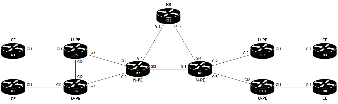
I’ll use the following topology:
Terms
| Term | Description |
|---|---|
| CE | Customer Edge |
| PE | Provider Edge |
| U-PE | User Provider Edge |
| N-PE | Network Provider Edge |
| UNI | User Network Interface |
| VFI | Virtual Forwarding Instance |
VFI is also called VSI (Virtual Switching Instance). Cisco uses the term VFI.
Introduction
VPLS is an MEF E-LAN service (MP2MP).
H-VPLS (Hierarchical Virtual Private LAN Service) is a way to scale VPLS. The issue with VPLS is that it requires a full mesh of PWs (pseudowires) between PEs. This doesn’t scale. In order to address this shortcoming, two types of PEs exist with H-VPLS: U-PE and N-PE. The User facing PE (U-PE) is the router connecting to the CE and the N-PE. Network facing PE peers with U-PEs and N-PEs. The U-PE only need to have a PW to the N-PE. But the N-PE still needs a full mesh of PWs to all other N-PEs, and also a PW to each U-PE.
Split Horizon
Since VPLS is a L2 service, special care must be taken to ensure that traffic doesn’t loop. L2 loops are deadly to a network. The reason why we need a full mesh between N-PEs has to do with split horizon. VPLS uses a virtual bridge port, called VFI (Virtual Forwarding Instance). This is where we terminate the PWs from other N-PEs. And if we were to send traffic received in on the VFI back out the VFI towards other N-PEs, a loop would be created:
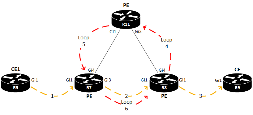
Here a packet is being forwarded from the CE on the left (R5). The receiving PE (R7) encapsulates the packet in MPLS and sends it out its PW towards the egress PE (R8). With split horizon turned off, R8 would not only decapsulate the packet and send it out to the receiving CE (R9), it would also loop the packet back out its VFI for this VPLS towards another PE (R11). Split horizon is also turned off on R11, hence the packet is looped back to R7. Now a unidirectional loop has been created in the SP core network!
So, to avoid this meltdown of the network, split horizon is turned on for PWs in the VFI.
Data Plane
MPLS is mandatory with VPLS. We use MPLS for VPLS the same way we use it for L3 VPNs. A stack of two labels is added to traffic received from a CE on the ingress PE. One label (top label) determines the transport in the SP core towards the egress PE. This is equivalent to how the Loopback interface of a PE in L3 VPNs is reached. Also, a VPN label is used to determine which VPLS the egress PE has to use to forward the traffic to the correct CE.
Control Plane
With VPLS we have these options:
VPN Discovery
- Manual
- BGP (Auto Discovery)
Signaling
- LDP
- BGP
Unless we configure it, VPLS uses Targeted LDP to signal the VPN label. BGP can be used both for AD (Auto Discovery) of the PEs and to provide VPN labels instead of LDP.
With H-VPLS certain restrictions regarding BGP AD apply. For example these ones:
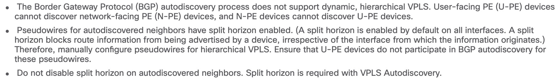
This should leave us with the possibility to use BGP AD between N-PEs. I’ll explore this later.
H-VPLS Configuration
Now its time to have a bit of fun with a H-VPLS lab.
I’ve already configured an IGP+LDP between all routers. Remember that VPLS requires MPLS. To support BGP AD, I’ll use R11 as RR:
! R11
router bgp 65000
 template peer-policy vpls-policy
  route-reflector-client
  send-community extended
 exit-peer-policy
 !
 template peer-session vpls-session
  remote-as 65000
  update-source Loopback0
 exit-peer-session
 !
 bgp router-id 11.11.11.11
 bgp log-neighbor-changes
 neighbor 7.7.7.7 inherit peer-session vpls-session
 neighbor 8.8.8.8 inherit peer-session vpls-session
 !
 address-family l2vpn vpls
  neighbor 7.7.7.7 activate
  neighbor 7.7.7.7 inherit peer-policy vpls-policy
  neighbor 8.8.8.8 activate
  neighbor 8.8.8.8 inherit peer-policy vpls-policy
 exit-address-family
R7 looks like this, and R8 is configure the same execpt for the BGP router ID:
! R7
router bgp 65000
bgp router-id 7.7.7.7
bgp log-neighbor-changes
neighbor 11.11.11.11 remote-as 65000
neighbor 11.11.11.11 update-source Loopback0
!
address-family l2vpn vpls
 neighbor 11.11.11.11 activate
 neighbor 11.11.11.11 send-community extended
exit-address-family
Verification of the peerings on R11:
R11#sh bgp l2vpn vpls all summary | be Neighbor
Neighbor        V           AS MsgRcvd MsgSent   TblVer  InQ OutQ Up/Down  State/PfxRcd
7.7.7.7         4        65000      73      76        3    0    0 01:00:29        1
8.8.8.8         4        65000      70      73        3    0    0 00:59:46        1
R11#
R11#sh bgp l2vpn vpls all | be Network
     Network          Next Hop            Metric LocPrf Weight Path
Route Distinguisher: 65000:1
 *>i 65000:1:7.7.7.7/96
                       7.7.7.7                  0    100      0 ?
 *>i 65000:1:8.8.8.8/96
                       8.8.8.8                  0    100      0 ?
R11#
The reason why we see this odd looking /96 NLRI in the BGP table is because of the RD (64-bit) and the IP address (32-bit). You might wonder where the RD comes from. To explain this, I’ll first have to show the VFI configuration:
! R7
l2vpn vfi context H-VPLS
 vpn id 1
 autodiscovery bgp signaling ldp
Here a vpn id is specified. In fact you must specify the vpn id before you can configure anything else under the VFI. The vpn id is essential, because it defines the id of this l2vpn service. It is also used as part of the RD in this format: ASN:VPN_ID (65000:1) as we can see in the BGP verification output of R11 above. With the VFI BGP AD default configuration, auto-route-target is enabled. This makes the RT the same value as the RD. We can see this by looking at the NLRI for R8 on R7:
R7#sh bgp l2vpn vpls rd 65000:1 8.8.8.8
BGP routing table entry for 65000:1:8.8.8.8/96, version 3
Paths: (1 available, best #1, table L2VPN-VPLS-BGP-Table)
Flag: 0x20
  Not advertised to any peer
  Refresh Epoch 2
  Local
    8.8.8.8 (metric 20) from 11.11.11.11 (11.11.11.11)
      Origin incomplete, metric 0, localpref 100, valid, internal, best, AGI version(2399141890)
      Extended Community: RT:65000:1 L2VPN AGI:65000:1
      Originator: 8.8.8.8, Cluster list: 11.11.11.11
      mpls labels in/out exp-null/exp-null
      rx pathid: 0, tx pathid: 0x0
R7#
If we look at a packet capture taken on R11’s Gi1 interface, we can also verify this:
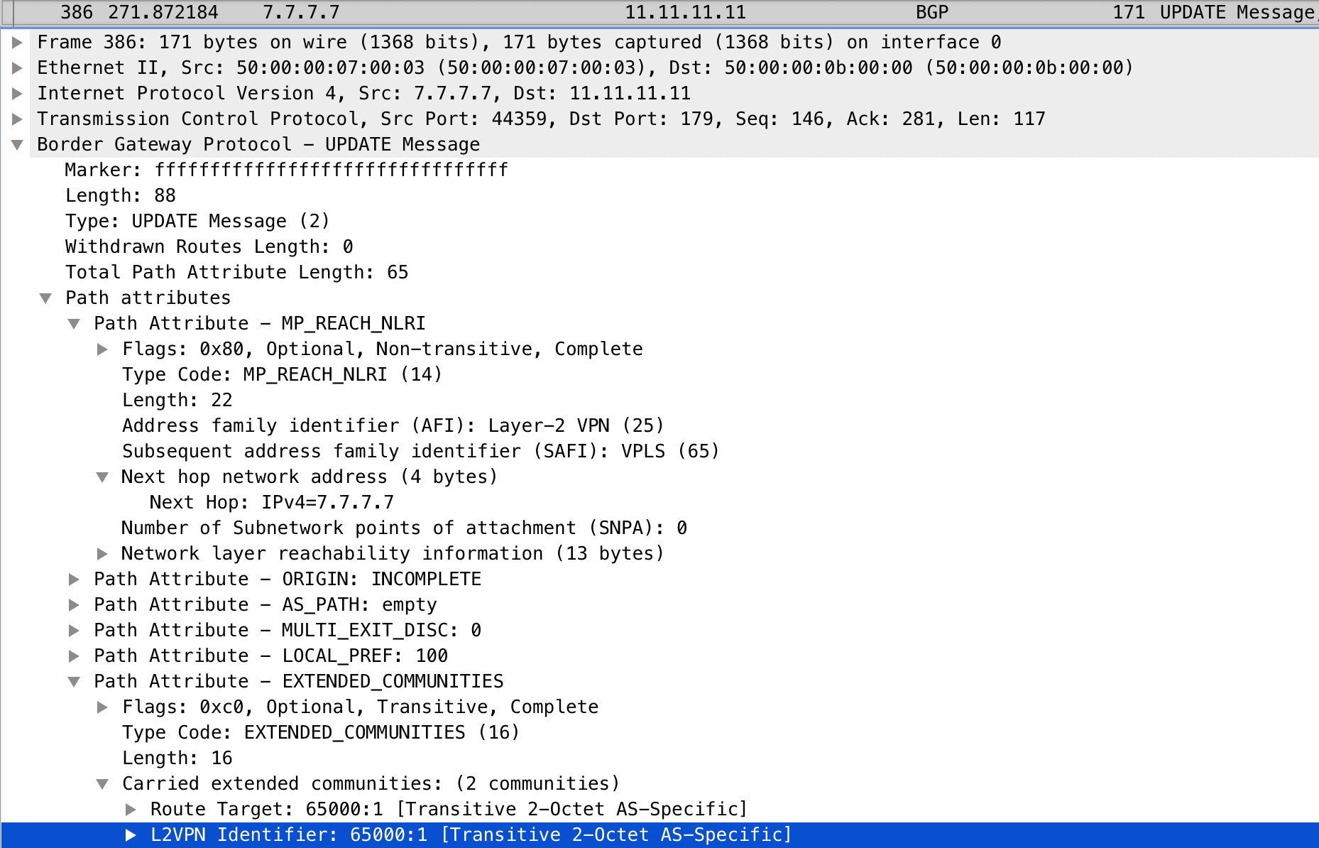
Again we see the 65000:1 value.
As soon as BGP AD has been configured under the VFI, we would like to see an LDP peering between R7 and R8:
%LDP-5-NBRCHG: LDP Neighbor 8.8.8.8:0 (3) is UP
To verify split horizon we can look at the VFI:
R7#sh vfi
Legend: RT=Route-target, S=Split-horizon, Y=Yes, N=No

VFI name: H-VPLS, state: up, type: multipoint, signaling: LDP
 VPN ID: 1, VPLS-ID: 65000:1
 RD: 65000:1, RT: 65000:1
 Bridge-Domain 1 attachment circuits:
 Neighbors connected via pseudowires:
 Peer Address     VC ID        Discovered Router ID    S
 8.8.8.8          1            8.8.8.8                 Y
 6.6.6.6          1            n/a                     N
 5.5.5.5          1            n/a                     N

R7#
Split horizon is enabled towards our other N-PE, R8. It is disabled, however, towards R5 and R6. We’ll see how and why below.
Next we need a bridge domain to tie it all together. A bridge domain represents a L2 broadcast domain consisting of interfaces that share the same forwarding characteristics. We need it to be able to bridge traffic between both PWs and physical interfaces. The former is only used on the U-PE.
! R7
bridge-domain 1
 member vfi H-VPLS
 member 6.6.6.6 1 encapsulation mpls
 member 5.5.5.5 1 encapsulation mpls
This configuration is very similar to how you would configure PEs manually under a VFI. The reason why we configure the U-PEs under the bridge domain instead of under the VFI, is to disable split horizon for loop prevention. We want traffic to be forwarded further downstream towards our egress PE, the U-PE. Had we configured the U-PE under the VFI, traffic would not be sent out to any neighbors in that VFI once received. We can however bridge it out an interface, or to other PWs. This is essentially what makes VPLS hierarchical.
To finalize how we configure H-VPLS, let’s have a look at the U-PEs:
! R6
l2vpn vfi context VPLS
 vpn id 1
 member 7.7.7.7 encapsulation mpls
!
bridge-domain 1
 member GigabitEthernet1 service-instance 1
 member vfi VPLS
!
interface GigabitEthernet1
 no ip address
 negotiation auto
 service instance 1 ethernet
  encapsulation default
The only difference here is that we have the UNI, Gi1. I’m a bit lazy here with my catch-all configuration of encapsulation default. This will match all ingress frames. If you configure other non-default service instances on the interface, the encapsultaion default command matches frames that are unmatched by those non-default service instances - a catch-all essentially.
As a final verification, we should be able to see the MAC addresses of our CEs:
R6#sh bridge-domain 1
Bridge-domain 1 (2 ports in all)
State: UP                    Mac learning: Enabled
Aging-Timer: 300 second(s)
    GigabitEthernet1 service instance 1
    vfi VPLS neighbor 7.7.7.7 1
   AED MAC address    Policy  Tag       Age  Pseudoport
   0   5000.0002.0000 forward dynamic   281  GigabitEthernet1.EFP1
   0   5000.0003.0000 forward dynamic   278  VPLS.1004011
   0   5000.0004.0000 forward dynamic   285  VPLS.1004011
   1   FFFF.FFFF.FFFF flood   static    0    OLIST_PTR:0xe80f8400
   0   5000.0001.0000 forward dynamic   286  VPLS.1004011

R6#
Surely we see 5000.0002.0000 out Gi1 on R6. This is the MAC address of R2’s Gi1 interface. Also we see the MAC addresses of R1, R3, and R4 out a PW towards R7, our N-PE.
This wraps up how you configure H-VPLS. To make the article complete, I’ll include the configuration of R1 and R2:
! R1
interface GigabitEthernet1
 ip address 10.0.0.1 255.255.255.0
 ip ospf network point-to-multipoint
 ip ospf 1 area 0

! R2
interface GigabitEthernet1
 ip address 10.0.0.2 255.255.255.0
 ip ospf network point-to-multipoint
 ip ospf 1 area 0


R2#sh ip ospf neighbor

Neighbor ID     Pri   State           Dead Time   Address         Interface
4.4.4.4           0   FULL/  -        00:01:57    10.0.0.4        GigabitEthernet1
3.3.3.3           0   FULL/  -        00:01:50    10.0.0.3        GigabitEthernet1
1.1.1.1           0   FULL/  -        00:01:38    10.0.0.1        GigabitEthernet1
R2#
Now R1 and R2 can become OSPF adjacent over H-VPLS making the SP network transparent to the customer.
We can even take a look at the labels used. To demonstrate that we do in fact use a label stack just like with L3 VPNs, I’ll disable the link between R7 and R8, making the path between them go through R11, the RR, just to avoid PHP.
! R7
interface GigabitEthernet3
 ip address 10.0.78.7 255.255.255.0
 ip router isis
 shutdown
 negotiation auto
 isis network point-to-point
Now let’s take a look at the MPLS VC to R8:
R7#sh mpls l2transport vc destination 8.8.8.8 detail
Local interface: VFI H-VPLS vfi up
 Interworking type is Ethernet
 Destination address: 8.8.8.8, VC ID: 1, VC status: up
   Output interface: Gi4, imposed label stack {19 22}
   Preferred path: not configured
   Default path: active
   Next hop: 10.7.11.11
 Create time: 11:34:59, last status change time: 01:06:07
   Last label FSM state change time: 01:06:07
 Signaling protocol: LDP, peer 8.8.8.8:0 up
   Targeted Hello: 7.7.7.7(LDP Id) -> 8.8.8.8, LDP is UP
   Graceful restart: not configured and not enabled
   Non stop routing: not configured and not enabled
   Status TLV support (local/remote)   : enabled/supported
     LDP route watch                   : enabled
     Label/status state machine        : established, LruRru
     Last local dataplane   status rcvd: No fault
     Last BFD dataplane     status rcvd: Not sent
     Last BFD peer monitor  status rcvd: No fault
     Last local AC  circuit status rcvd: No fault
     Last local AC  circuit status sent: No fault
     Last local PW i/f circ status rcvd: No fault
     Last local LDP TLV     status sent: No fault
     Last remote LDP TLV    status rcvd: No fault
     Last remote LDP ADJ    status rcvd: No fault
   MPLS VC labels: local 22, remote 22
   AGI: type 1, len 8, 000A FDE8 0000 0001
   Local AII: type 1, len 4, 0707 0707 (7.7.7.7)
   Remote AII: type 1, len 4, 0808 0808 (8.8.8.8)
   Group ID: local n/a, remote n/a
   MTU: local 1500, remote 1500
   Remote interface description:
 Sequencing: receive disabled, send disabled
 Control Word: On (configured: autosense)
 SSO Descriptor: 8.8.8.8/1, local label: 22
 Dataplane:
   SSM segment/switch IDs: 24590/4106 (used), PWID: 4
 VC statistics:
   transit packet totals: receive 0, send 3710
   transit byte totals:   receive 0, send 480685
   transit packet drops:  receive 3056, seq error 0, send 0


R7#
A lot of information is included in this output. I keep the complete output for reference. Here is a more relevant filtered output:
R7#sh mpls l2transport vc destination 8.8.8.8 detail | in VFI|VC_ID|stack|labels
Local interface: VFI H-VPLS vfi up
  Destination address: 8.8.8.8, VC ID: 1, VC status: up
    Output interface: Gi4, imposed label stack {19 22}
    MPLS VC labels: local 22, remote 22
R7#
For this VFI we impose a label stack of {19 22} when forwarding traffic towards R8. Our local label for this VC ID is 22 which happens to be the same value as the one received by R8.
The transport label, 19, can be verified by looking a the LFIB on R7:
R7#sh mpls forwarding-table 8.8.8.8 32
Local      Outgoing   Prefix           Bytes Label   Outgoing   Next Hop
Label      Label      or Tunnel Id     Switched      interface
18         19         8.8.8.8/32       0             Gi4        10.7.11.11
R7#sh ip cef 8.8.8.8/32
8.8.8.8/32
  nexthop 10.7.11.11 GigabitEthernet4 label 19
R7#
If we look at a packet capture on R11’s Gi1 interface, we should be able to see these labels:
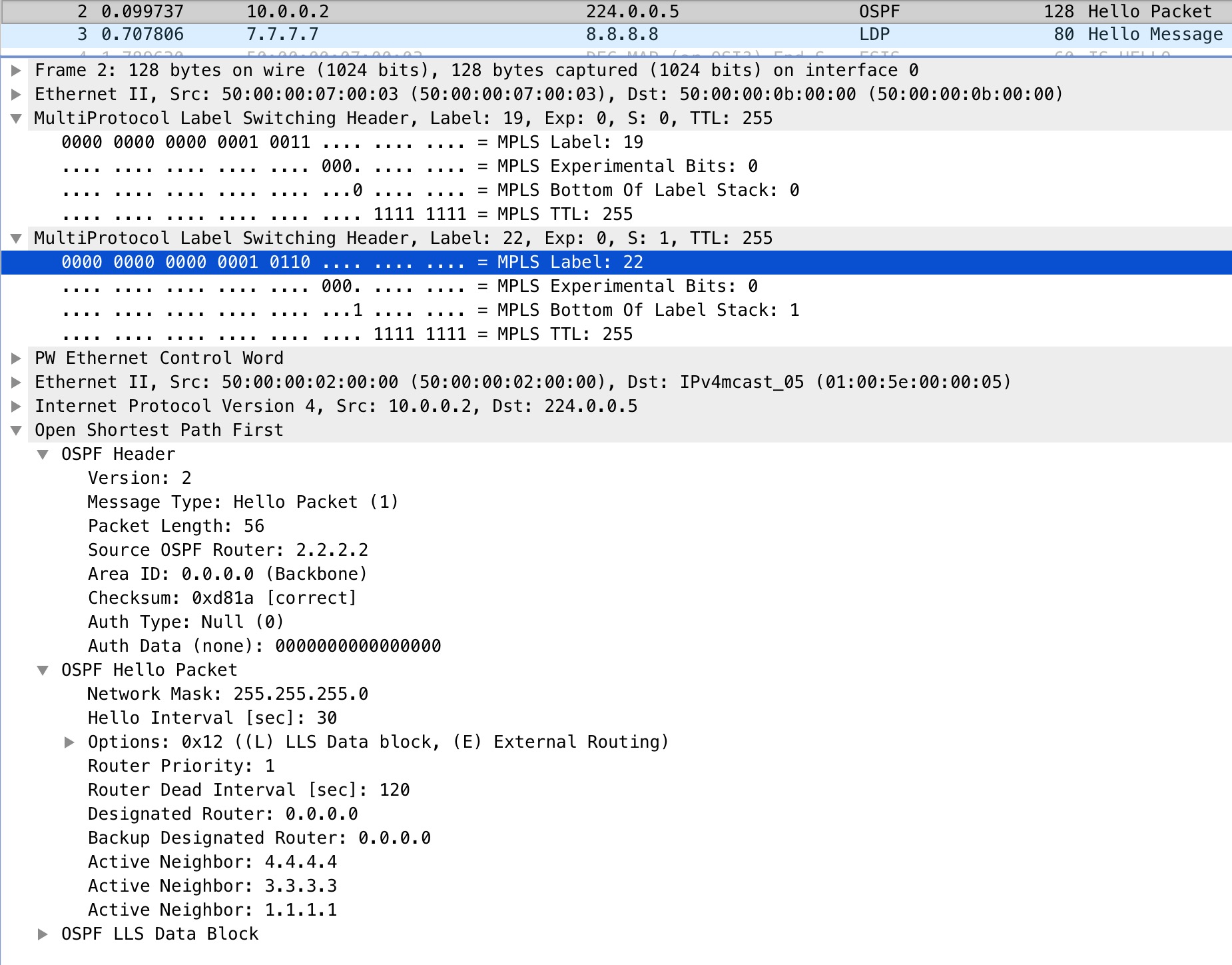
Here we see the verification of our label stack of 19, our top most label, and 22, our VPN label for the VC. We also see how the entire L2 frame is encapsulated in MPLS.
Conclusion
To sum up, with H-VPLS, our N-PEs still need a full mesh of PWs between them. BGP Auto Discovery helps us by not having to configure a full mesh of PWs between our PEs manually. To circumvent split horizon on the VFI, we define the U-PEs under the bridge domain of our N-PEs. The peering between N-PEs and U-PEs are manually defined as BGP AD isn’t supported here.
That it. I hope you enjoyed reading this post.