Classical Enterprise LAN Design - Part II
Table of Contents
This post delves into the pros and cons of another classical enterprise LAN design. Focus is on detailing why you might choose such a design and the workings of it. A few optimizations are shown, too.
For Part I check out Classical Enterprise LAN Design - Part I
Topology
Below topology is the starting point. Some choices have been taken as described in the green boxes.
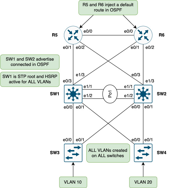
SW1 and SW2 are distribution switches that mark the demarcation between L2/L3 from access to the rest of the network (core). An FHRP is needed to provide gateway redundancy for the access layer. Without it we’d either not have the needed redundancy or overlapping IPs since the two switches see each other on the same L2 segment.
Currently SW1 has the active HSRP role and is root for all STP instances. It is important to ensure the STP root is also on the HSRP active node. Had SW2 been the STP root, traffic would need to traverse SW2 before reaching SW1 (the gateway) which is sub-optimal.
North of SW1 and SW2 OSPF is configured in Area 0 between these neighbors:
- SW1 <-> R5
- SW1 <-> R6
- SW2 <-> R5
- SW2 <-> R6
- R5 <-> R6
SW1 and SW2 do redistribution of connected to advertise the SVIs for endpoint reachability. R5 and R6 inject a default route for reachability upstream.
Note that currently no routing is configured between SW1 and SW2. The LAG (Po1) between these switches run L2-only.
All inter-switch links are trunks and all VLANs are allowed on them (no pruning of VLANs anywhere).
A per-switch VLAN has been created to try and keep VLANs localized per access switch. Not shown in the topology could be a VLAN that needs stretching due to legacy applications requiring broadcast or due to roaming of WIFI. For now, focus is on the shown topology.
This topology is made up of triangles between an access switch (SW3 or SW4) and the two distribution switches, SW1 and SW2.
# Why Choosing to have this type of design comes with some technical advantages compared to the square topology we saw in Part I:
- Optimal paths using the direct uplink towards the STP root and HSRP active node
- Optimized (less) oversubscription
On the positive side this design allows for extending VLANs across the access switches. Though not recommended this is sometimes needed for legacy applications and stuff like BMS such as HVAC. And WIFI roaming as mentioned previously.
Non-technical benefits of this design:
- Dependencies
- Simplicity
- Risk Spread
Each is detailed in below sections.
Dependencies
Less dependencies among components (no daisy chaining of access switches) which lead to a more predictable and hence more stable network with less moving parts so to speak.
Simplicity
Simpler network to operate, maintain, and troubleshoot.
Risk Spread
Having two independent distribution switches removes fate-sharing between them as their management plane and control plane are completely separated. This makes it less likely that you will end up with both being problematic at the same time.
Also, when performing upgrades, you can safely take one switch at a time without causing much disruption to the traffic. Some people find this very reassuring. Especially when the equipment sits halfway around the world.
Downsides
From a non-technical perspective the only downside (that I could think of) is:
- Cost
Detailed in below section.
Cost
Somewhat higher cost with all access switches connecting to both distribution switches. The port-count in the distribution switches is higher which might also add to the cost of this design.
Issues
Every design has downsides. This section addresses the technical aspecets of these issues.
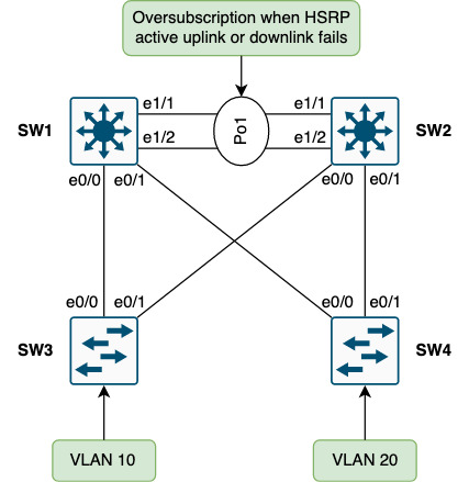
Issue #1 - Oversubscription
With every access switch linking directly to each distribution switch, the oversubscription is minimal, but present:
From the perspective of R5 and R6, load sharing is going on:
! R5:
R5#sh ip cef 10.0.10.0
10.0.10.0/24
  nexthop 10.0.15.1 Ethernet0/1
  nexthop 10.0.25.2 Ethernet0/2
R5#traceroute 10.0.10.3 numeric timeout 1
Type escape sequence to abort.
Tracing the route to 10.0.10.3
VRF info: (vrf in name/id, vrf out name/id)
  1 10.0.15.1 1 msec
    10.0.25.2 0 msec
    10.0.15.1 0 msec
  2 10.0.10.3 1 msec *  1 msec
R5#

! R6:
R6#sh ip cef 10.0.10.0
10.0.10.0/24
  nexthop 10.0.16.1 Ethernet0/1
  nexthop 10.0.26.2 Ethernet0/2
R6#traceroute 10.0.10.3 numeric timeout 1
Type escape sequence to abort.
Tracing the route to 10.0.10.3
VRF info: (vrf in name/id, vrf out name/id)
  1 10.0.16.1 1 msec
    10.0.26.2 0 msec
    10.0.16.1 1 msec
  2 10.0.10.3 1 msec *  2 msec
R6#
This means that some flows will land on SW1 and some on SW2. This is one of the benefits of routing - being able to use more than one link. The issue lies in a failure of either an uplink or a downlink of the HSRP active node, SW1 in this case.
In case the uplink on SW1 to R5 is lost, packets from R5 will be forwarded to SW2 which will switch them through SW1:
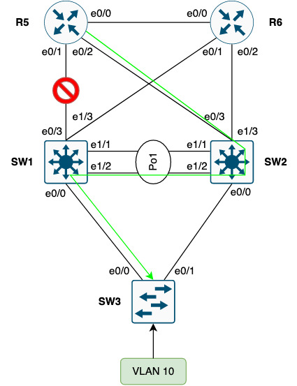
Some packets from R6 will still be forwarded directly to SW1, though.
And if the downlink from SW1 to SW3 fails, some packets from R5 will still be forwarded to SW1 which will switch them through SW2:
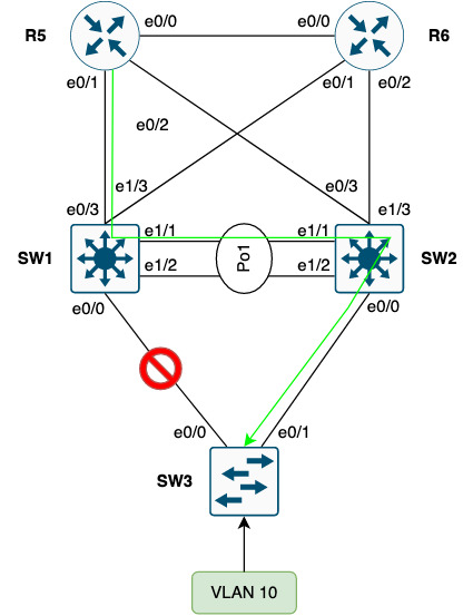
The same goes for packets from R6 to SW1.
Issue #2 - Link Underutilization
Layer 2 and multipath do not go hand in hand. With no TTL and no control plane to calculate loop free (multi)paths, layer 2 must rely on STP blocking redundant links:
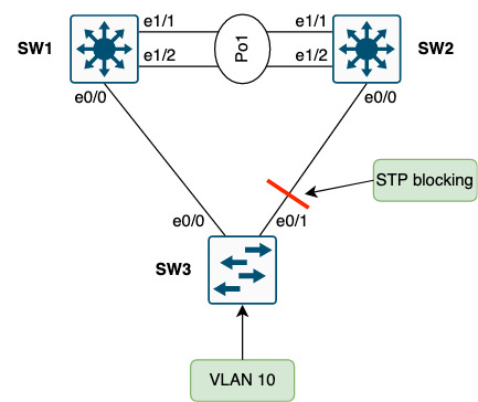
Here, SW3 will block the uplink to SW2 to break the physical loop of Vlan10. This means that this uplink cannot be used by SW3. SW4 will do the same for Vlan20.
! SW3:
SW3#sh spanning-tree vlan 10 blockedports

Name                 Blocked Interfaces List
-------------------- ------------------------------------
VLAN0010             Et0/1

Number of blocked ports (segments) in vlan 10: 1

SW3#sh cdp nei e0/1 | be ^Device
Device ID        Local Intrfce     Holdtme    Capability  Platform  Port ID
SW2              Eth 0/1           168             R S I  Linux Uni Eth 0/0

Total cdp entries displayed : 1
SW3#
Note that SW2’s downlink to SW3 (and SW4) is not blocking, meaning it can send traffic down these links:
! SW2:
SW2#sh span vlan 10 blockedports

Name                 Blocked Interfaces List
-------------------- ------------------------------------

Number of blocked ports (segments) in vlan 10: 0

SW2#
SW3, however, will not be able to learn the MAC addresses of the sources if any such traffic were to be received on this uplink. Forwarding entries with classical L2 is data plane driven, meaning we only create/update the CAM table upon receiving traffic. Traffic for broadcast, unknown unicast, and multicast (BUM) is flooded out all ports except the one it arrived on. This behaviour is needed to be able to build up the forwarding tables and learn about the location of endpoints.
In effect this causes redundant uplinks to be underutilized because they are unusable due to STP blocking them. This is inherent to L2 networks and not just an issue with this specific design.
Issue #3 - Downstream Pack Flood
When traffic for Vlan10 arrives at SW2 the ARP cache is checked:
! SW2:
SW2#sh ip arp vlan 10 | in 10.0.10.3
Internet  10.0.10.3              50   aabb.cc80.3000  ARPA   Vlan10
SW2#
10.0.10.3 is the SVI of SW3… Next, the packet is switched using the CAM (MAC address table):
! SW2:
SW2#sh mac address-table address aabb.cc80.3000 vlan 10
          Mac Address Table
-------------------------------------------

Vlan    Mac Address       Type        Ports
----    -----------       --------    -----
SW2#
No entries exist for 10.0.10.3’s MAC address which means that SW2 must flood the packet out all trunk ports. This phenomenon is called “Downstream Pack Flood” and is highly unwanted.
Here is a packet capture taken on SW3’s uplink (e0/1) to SW2 while pinging 10.0.10.3 (SW3’s SVI in Vlan10) from R5’s Loopback (5.5.5.5):
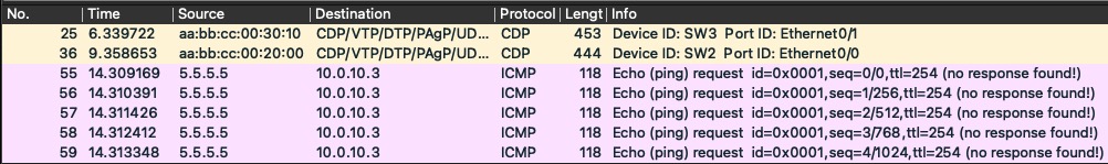
Since SW2 has all ports in STP forwarding state, the packet is flooded down the link to SW3. This happens because SW2 does not see traffic from Vlan10 (not HSRP active role or in L2 path). In fact, the SW3’s uplink to SW2 is in STP blocking state:
! SW3:
SW3#sh spanning-tree vlan 10

VLAN0010
  Spanning tree enabled protocol rstp
  Root ID    Priority    24586
             Address     aabb.cc00.1000
             Cost        100
             Port        1 (Ethernet0/0)
             Hello Time   2 sec  Max Age 20 sec  Forward Delay 15 sec

  Bridge ID  Priority    32778  (priority 32768 sys-id-ext 10)
             Address     aabb.cc00.3000
             Hello Time   2 sec  Max Age 20 sec  Forward Delay 15 sec
             Aging Time  300 sec

Interface           Role Sts Cost      Prio.Nbr Type
------------------- ---- --- --------- -------- --------------------------------
Et0/0               Root FWD 100       128.1    P2p
Et0/1               Altn BLK 100       128.2    P2p


SW3#
Inter-distribution Switch Link Importance
You might ask yourself why we need the link between SW1 and SW2. HSRP will work if we don’t have it. So why is this link needed?
Consider an uplink failure on SW3:
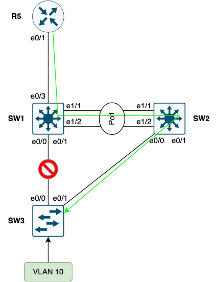
It is clear that without this inter-distribution switch link traffic for Vlan10 cannot be forwarded to SW3.
Ok, so we need the link, but should it be L2 or L3?
If you make the inter-connection link L3-only, you mandate that Vlan10 be available only on SW3. For this you’ll need tightly controlled VLAN pruninng on all trunks. If Vlan10 is allowed on any of the remaining trunk links, the subnet will be advertised upstream, but SW1 will not be able to forward traffic to the Vlan10 endpoints of SW3 (SW1 will try to ARP for the destination and we have no L2 path). Also, I stated earlier that all VLANs are allowed on all inter-switch links, so L3 alone wouldn’t be feasible.
So, the inter-distribution link is very important and it must be L2 and carry all VLANs for this design.
Optimization and Solutions
Though this is technically a better design than using squares there is still room for improvement and optimizations. This section shows suggestions on how to further enhance the design we started out with.
Link Utilization and Oversubscription
Currently all uplinks to SW2 are blocked by each access switch. Luckily Cisco has implemented instances with STP. In this setup we run RSTP which has an instance per VLAN. This means we can make SW2 the STP root for some of the VLANs:
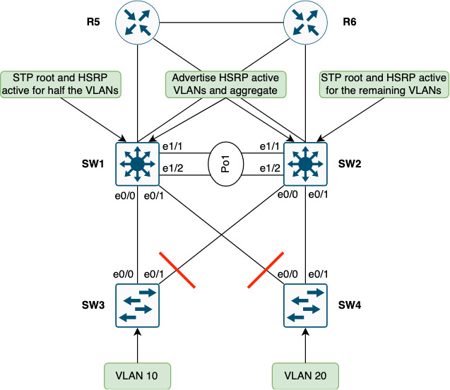
Note the aggregation and filtering of non-HSRP active VLANs on SW1 and SW2.
With this tweak we’ve gained two things:
- Utilized the before blocked redundant link on approximately half the switches in our network
- Ingress routing follows the STP root and HSRP active node
The first point might not seem so obvious, but for traffic leaving the site, the links between SW2 and the edge routers (R5 and R6) would have been idle for traffic egress of SW2. In fact, the traffic was forwarded asymmetrically with some traffic ingressing on SW2, but no traffic egressing on SW2. This can cause issues with jitter which some applications are susceptible to - voice being one such example.
The second point regarding ingress routing deals with how traffic is forwarded across the inter-distribution link when ingressing on the non-HSRP active peer (the standby node). By keeping routing aligned with the HSRP active role we ensure that ingress traffic is forwarded downstream directly, becuase the HSRP active node is also the STP root.
Note there is no need to establish a L3 peering between SW1 and SW2 as they both have dual uplinks, meaning even if one uplink or upstream router fails, traffic can still be forwarded (and received from) upstream.
Downstream Pack Flood
The downstream pack flood issue is a commonly overlooked problem. Furtunately the fix is fairly simple:
- Set ARP timeout equal to the CAM timeout on the non-HSRP active node (the standby node)
Below is the current (and default) CAM timer for Vlan10 which is supposed to be non-HSRP active or HSRP standby on SW2.
! SW2:
SW2#sh mac address-table aging-time vlan 10
Global Aging Time:  300
Vlan    Aging Time
----    ----------
  10     300

SW2#
The value is in seconds, meaning 5 minutes. We adjust the ARP timer for Vlan10 on SW2 to be the same:
! SW2:
interface Vlan10
 arp timeout 300

SW2#sh int vlan 10 | in ARP Timeout|Vlan
Vlan10 is up, line protocol is up
  ARP type: ARPA, ARP Timeout 00:05:00
SW2#
This makes the ARP entry age out roughly at the same time as the CAM entry forcing the switch to do an ARP request instead of flooding the traffic.
Open Issues
Dispite optimizing link utilization we still have blocking links. But for the most part this design works quite well.
Conclusion
During this post we found out that although using triangles instead of squares for enterprise LAN networks is far superior, there is still room for improvement and tweaks. These issues were addressed:
- Oversubscription
- Link Underutilization
- Downstream Pack Flood
Moreover the importance of the inter-distribution switch link was discussed. It ensures forwarding downstream can happen when an uplink fails from an access switch. And the link must be L2 to keep things simple and working.
Finally we saw how you can optimize this network’s link utilization and oversubscription using small adjustments:
- Load distribution of STP root and HSRP active role between SW1 and SW2
- Ingress traffic engineering using shortest prefix length routing
From a business point of view the following were highlighted:
- Less dependencies lead to a more predictable and stable network (incurs less downtime)
- Simplicity to help operate, maintain, and troubleshoot
- Risk Spread to remove fate-sharing between the distribution swithes
All points are beneficial for ensuring the stability of the network to better support the business operations.
I hope you found this post useful. Thanks for reading.