EVPN on Catalyst - Multihoming
Table of Contents
Continuing from my previous and first post on EVPN on Catalyst - Layer 2 we’re looking in to multihoming with EVPN on Catalyst. This post will only show the multihoming related configuration. For full EVPN L2 config check out my first post.
Redundancy is essential to ensuring business continuity in today’s infrastructures. EVPN has the ability to provide link and node redundancy for both devices and networks. It comes in two flavors:
- Single-active
- All-active
As of writing only single-active is supported. The all-active option is still in EFT. I will shown you both options as I’m part of the EFT for this feature. The feature is GA in IOS XE version 17.18.2.
Be aware that once you configure multihoming on a port, that port stops running STP. For a VTEP other mechanisms handle loop prevention as we will see later.
Ethernet Segment Identifier (ESI)
In EVPN an ethernet segment (ES) is merely the link connecting to the CE. Each ES has an identifier, the ethernet segment identifier (ESI), which is made of two parts: Type and Value. It has a length of 10 octets. Below is a table that describes the different ESIs generally used.
| Deployment | Type | Value |
|---|---|---|
| Single-homed | 0 | 000000000 |
| Single-active | 0 | An arbitrary 9-octet ESI value supplied by the operator. Example: 123456789 |
| Single-active | 3 | A MAC-based ESI that contains a 6-byte system MAC address and a 3-type local value |
| All-active | 1 | CE LACP system MAC (6 bytes) + CE LACP port key (2 bytes) + 0 (1 byte) (example: 01AA.BBCC.8011.0000.0100) |
Each ESI must be unique network wide.
Ethernet Tag ID
An Ethernet Tag identifies a broadcast domain (VLAN). With Cisco’s implementation on IOS XE there is a one-to-one mapping between an EVI and a VLAN. This is called a VLAN-based Service Interface per the RFC and requires the Ethernet Tag ID be set to 0 (zero).
EVPN Route Types
EVPN has many use cases. It would be inefficient to encode all options in a single BGP update. Hence, the standard came up with four different route types to signal various functions of EVPN for Layer 2. With L3 a fifth route type exists (Route Type 5). Below is a table describing each of the four route types. This post focusses on route types 1,2, and 4. Each are explained in detail following the table.
| Route Type | Name | Contains |
|---|---|---|
| 1 | Ethernet Auto-Discovery (A-D) route | ESI, Ethernet Tag ID |
| 2 | MAC/IP Advertisement route | Ethernet Tag ID, MAC address, IP address |
| 3 | Inclusive Multicast Ethernet Tag route | Ethernet Tag ID, Originating Router’s IP address |
| 4 | Ethernet Segment route | ESI, Originating Router’s IP address |
All EVPN NLRIs start with the RD.
Route Type 1 - Ethernet Auto-Discovery (EAD) route
The EAD route is used in multi-homing for aliasing, fast convergence, and split horizon. There are two message types:
- EAD per EVI
- Used for aliasing
- EAD per ES
- Used for fast convergence
- Used for split horizon
- Not needed for single-active
- RD must be in format “IP:n” (RD type 1). Typically uses a loopback address and is typically auto-generated
- Ethernet Tag ID must be set to MAX-ET (0xFFFFFFFF (4294967295))
- MPLS Label must be set to 0 (zero)
- The ESI Label extended community must be included and:
- Flag = 0x0 means all-active
- Flag = 0x1 means single-active
- ESI Label must be set to 0 (zero)
NOTE! Both the EAD per EVI and the EAD per ES must be received
Example of EAD per EVI NLRI
BGP routing table entry for [1][100.127.1.1:123][01AABBCC801100000100][0]/23, version 109
Paths: (1 available, best #1, table EVPN-BGP-Table)
  Not advertised to any peer
  Refresh Epoch 1
  Local
    100.127.1.1 (metric 20) (via default) from 100.127.0.101 (100.127.0.101)
      Origin incomplete, metric 0, localpref 100, valid, internal, best
      Rcvd Label: 10123, Local Label: None
      Extended Community: RT:65000:123 ENCAP:8
      Originator: 100.127.0.1, Cluster list: 100.127.0.101
      rx pathid: 0, tx pathid: 0x0
      Updated on Dec 1 2025 11:49:54 UTC
Notice the RD consists of the source interface of the NVE interface, typically Loopback1, and the EVI instance number.
Example of EAD per ES NLRI
BGP routing table entry for [1][100.127.1.1:6][01AABBCC801100000100][4294967295]/23, version 108
Paths: (1 available, best #1, table EVPN-BGP-Table)
  Not advertised to any peer
  Refresh Epoch 1
  Local
    100.127.1.1 (metric 20) (via default) from 100.127.0.101 (100.127.0.101)
      Origin incomplete, metric 0, localpref 100, valid, internal, best
      Rcvd Label: 0, Local Label: None
      Extended Community: RT:65000:123 ENCAP:8 EVPN LABEL:0x0:Label-0
      Originator: 100.127.0.1, Cluster list: 100.127.0.101
      rx pathid: 0, tx pathid: 0x0
      Updated on Dec 1 2025 11:49:54 UTC
Notice the RD consists of the source interface of the NVE interface, typically Loopback1, and a number generated by the VTEP (6 in this case). Also, this particular example shows an all-active EAD per ES NLRI.
Aliasing
Using EAD per EVI route, aliasing allows a VTEP til signal that it has reachability to an EVPN instance on a given ES even when it has learned no MAC addresses from that EVI/ES. This allows remote VTEPs to use all egress VTEPs that have advertised reachability to the EVI/ES.
Have a look at the following image:
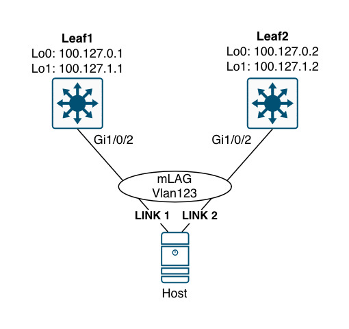
Here, the host is configured with a LAG that bundles link 1 and link 2 in one logical interface. Now, depending on the hash result link 2 might not be used to begin with. If this is the case, then Leaf2 would not learn the MAC address of the host, but it still has reachability to it. This is what aliasing addresses.
Essentially, aliasing allows load sharing to happen between egress VTEPs.
Fast Convergence
The EAD per ES route is used to signal mass withdrawal when a link fails. Instead of sending withdrawals for each Type 2 route (MAC and MAC/IP), a single withdrawal of the EAD per ES route can be sent. This will trigger all VTEPs to update their next-hop adjacencies for all MAC addresses associated with the ES in question. If no other VTEP had advertised an EAD route for the same segment, then the VTEP that received the withdrawal simply invalidates the MAC entries for that segment. Otherwise, the VTEP updates its next-hop accordingly.
Split Horizon
BUM traffic is flooded throughout the fabric reaching all VTEPs - including the other VTEP that is also connected to the same ES where the sender of the traffic is located. Split horizon prevents the traffic from looping back down to the host that originated the traffic. It works by including the Label received from the EAD per ES route. Obviously, VXLAN which is the data plane protocol used in enterprise networks with EVPN cannot carry the ESI label. Therefore, the other VTEP filters the packet based on the source VTEP’s IP. It can do that because of the EAD route’s next hop IP. This function reminds me of uRPF and RPF check for multicast.
Route Type 2 - MAC/IP Advertisement Route
With EVPN MAC remote addresses are learned using the route type 2. Initially a remote VTEP learned the MAC address based on the data plane when receiving traffic from the host using either DHCP or ARP packets. Once a VTEP learns the MAC address, it constructs the type 2 route and sends a BGP EVPN update.
Optionally, a type 2 route can carry an IP address. Cisco will actually create an additional update when it learns the IP address of a host and advertise it along with the MAC address thereby having two NLRIs for the host (one with just the MAC address and another with both the MAC and IP addresses). Knowing the IP address is handy when optimizing the ARP process with ARP suppression (ARP proxy).
Route Type 4 - Ethernet Segment route
The ES route is used for Designated Forwarder (DF) election in multi-homing. A DF is needed for BUM traffic not to loop. Only one VTEP can be responsible for forwarding BUM traffic towards a multi-homed device or network. The DF is elected per ES, Vlan, meaning you can have one VTEP elected as DF for Vlan11 and another elected as DF for Vlan12. This is called service carving. A non-DF will receive the BUM traffic but drop it to avoid forwarding loops.
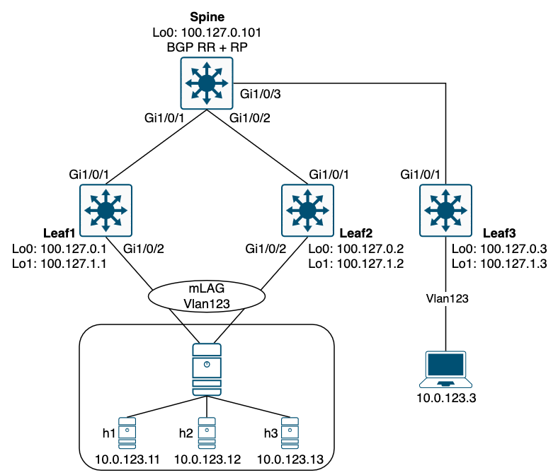
EVPN Single-active Multihoming
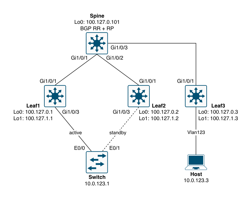
Below is a topology to demonstrate the EVPN multihoming single-active method.
! single-active:
vlan configuration 123
 member evpn-instance 123 vni 10123
!
l2vpn evpn ethernet-segment 123
 identifier type 0 01.02.03.04.05.06.07.08.09
 redundancy single-active
!
default int gi1/0/3
interface GigabitEthernet1/0/2
 switchport access vlan 123
 switchport mode access
 evpn ethernet-segment 123
With this configuration, the BGP table for L2VPN EVPN looks like this:
Leaf1#sh bgp l2vpn evpn | be Network
     Network          Next Hop            Metric LocPrf Weight Path
Route Distinguisher: 100.127.1.1:7
 *>   [1][100.127.1.1:7][00010203040506070809][4294967295]/23
                      0.0.0.0                            32768 ?
Route Distinguisher: 100.127.1.1:123
 *mi  [1][100.127.1.1:123][00010203040506070809][0]/23
                      100.127.1.2              0    100      0 ?
 *>                    0.0.0.0                            32768 ?
Route Distinguisher: 100.127.1.2:4
 *>i  [1][100.127.1.2:4][00010203040506070809][4294967295]/23
                      100.127.1.2              0    100      0 ?
Route Distinguisher: 100.127.1.2:123
 *>i  [1][100.127.1.2:123][00010203040506070809][0]/23
                      100.127.1.2              0    100      0 ?
Route Distinguisher: 100.127.1.1:123
 *>i  [2][100.127.1.1:123][0][48][AABBCC002910][0][*]/20
                      100.127.1.2              0    100      0 ?
Route Distinguisher: 100.127.1.2:123
 *>i  [2][100.127.1.2:123][0][48][AABBCC002910][0][*]/20
                      100.127.1.2              0    100      0 ?
Route Distinguisher: 100.127.0.1:2057
 *>   [4][100.127.0.1:2057][00010203040506070809][32][100.127.1.1]/23
                      0.0.0.0                            32768 ?
     Network          Next Hop            Metric LocPrf Weight Path
Route Distinguisher: 100.127.0.2:2057
 *>i  [4][100.127.0.2:2057][00010203040506070809][32][100.127.1.2]/23
                      100.127.1.2              0    100      0 ?
Leaf1#
The first number in the square brackets shows the route type. Here we have seen some traffic from the Switch with a MAC address of AABBCC002910. Let’s verify:
Switch#sh int vlan 123 | in Vlan|Hardware
Vlan123 is up, line protocol is up , Autostate Enabled
  Hardware is Ethernet SVI, address is aabb.cc80.2900 (bia aabb.cc80.2900)
Indeed the MAC address is from that interface. Now, when I ping the host, the leafs will learn about the IP of the Switch as well as both the MAC address and IP of the host.
Route Distinguisher: 100.127.1.1:123
 *>i  [2][100.127.1.1:123][0][48][AABBCC001130][0][*]/20
                      100.127.1.3              0    100      0 ?
 *>i  [2][100.127.1.1:123][0][48][AABBCC001130][32][10.0.123.3]/24
                      100.127.1.3              0    100      0 ?
 *>i  [2][100.127.1.1:123][0][48][AABBCC002910][0][*]/20
                      100.127.1.2              0    100      0 ?
 *>i  [2][100.127.1.1:123][0][48][AABBCC802900][0][*]/20
                      100.127.1.2              0    100      0 ?
 *>i  [2][100.127.1.1:123][0][48][AABBCC802900][32][10.0.123.1]/24
                      100.127.1.2              0    100      0 ?
Route Distinguisher: 100.127.1.2:123
 *>i  [2][100.127.1.2:123][0][48][AABBCC002910][0][*]/20
                      100.127.1.2              0    100      0 ?
 *>i  [2][100.127.1.2:123][0][48][AABBCC802900][0][*]/20
                      100.127.1.2              0    100      0 ?
 *>i  [2][100.127.1.2:123][0][48][AABBCC802900][32][10.0.123.1]/24
                      100.127.1.2              0    100      0 ?
Route Distinguisher: 100.127.1.3:123
 *>i  [2][100.127.1.3:123][0][48][AABBCC001130][0][*]/20
                      100.127.1.3              0    100      0 ?
 *>i  [2][100.127.1.3:123][0][48][AABBCC001130][32][10.0.123.3]/24
     Network          Next Hop            Metric LocPrf Weight Path
                      100.127.1.3              0    100      0 ?
The reason we see what looks like duplicates is because the NLRI is imported from the global BGP EVPN table to the BGP EVPN EVI table. Let’s have a look:
Leaf1#sh bgp l2vpn evpn AABBCC001130
BGP routing table entry for [2][100.127.1.1:123][0][48][AABBCC001130][0][*]/20, version 160
Paths: (1 available, best #1, table evi_123)
  Not advertised to any peer
  Refresh Epoch 3
  Local, imported path from [2][100.127.1.3:123][0][48][AABBCC001130][0][*]/20 (global)
    100.127.1.3 (metric 20) (via default) from 100.127.0.101 (100.127.0.101)
      Origin incomplete, metric 0, localpref 100, valid, internal, best
      EVPN ESI: 00000000000000000000, Label1 10123
      Extended Community: RT:65000:123 ENCAP:8
      Originator: 100.127.0.3, Cluster list: 100.127.0.101
      rx pathid: 0, tx pathid: 0x0
      Updated on Dec 8 2025 11:26:02 UTC
BGP routing table entry for [2][100.127.1.1:123][0][48][AABBCC001130][32][10.0.123.3]/24, version 166
Paths: (1 available, best #1, table evi_123)
  Not advertised to any peer
  Refresh Epoch 3
  Local, imported path from [2][100.127.1.3:123][0][48][AABBCC001130][32][10.0.123.3]/24 (global)
    100.127.1.3 (metric 20) (via default) from 100.127.0.101 (100.127.0.101)
      Origin incomplete, metric 0, localpref 100, valid, internal, best
      EVPN ESI: 00000000000000000000, Label1 10123
      Extended Community: RT:65000:123 ENCAP:8
      Originator: 100.127.0.3, Cluster list: 100.127.0.101
      rx pathid: 0, tx pathid: 0x0
      Updated on Dec 8 2025 11:26:20 UTC
BGP routing table entry for [2][100.127.1.3:123][0][48][AABBCC001130][0][*]/20, version 159
Paths: (1 available, best #1, table EVPN-BGP-Table)
  Not advertised to any peer
  Refresh Epoch 3
  Local
    100.127.1.3 (metric 20) (via default) from 100.127.0.101 (100.127.0.101)
      Origin incomplete, metric 0, localpref 100, valid, internal, best
      EVPN ESI: 00000000000000000000, Label1 10123
      Extended Community: RT:65000:123 ENCAP:8
      Originator: 100.127.0.3, Cluster list: 100.127.0.101
      rx pathid: 0, tx pathid: 0x0
      Updated on Dec 8 2025 11:26:02 UTC
BGP routing table entry for [2][100.127.1.3:123][0][48][AABBCC001130][32][10.0.123.3]/24, version 165
Paths: (1 available, best #1, table EVPN-BGP-Table)
  Not advertised to any peer
  Refresh Epoch 3
  Local
    100.127.1.3 (metric 20) (via default) from 100.127.0.101 (100.127.0.101)
      Origin incomplete, metric 0, localpref 100, valid, internal, best
      EVPN ESI: 00000000000000000000, Label1 10123
      Extended Community: RT:65000:123 ENCAP:8
      Originator: 100.127.0.3, Cluster list: 100.127.0.101
      rx pathid: 0, tx pathid: 0x0
      Updated on Dec 8 2025 11:26:20 UTC
Leaf1#
For AABBCC001130 we have two EVPN type 2 NLRIs:
- One contains just the MAC address of the Host
- One contains both the MAC and IP addresses of the Host
If the Host had run IPv6 an additional MAC/IP NLRI would exist.
We see that from the table EVPN-BGP-Table both these exist. Both have a RT (Route Target) of 65000:123. They were originated by 100.127.1.3 which is Leaf3 where the Host is connected. Because we have a matching import RT the routes are imported into the table evi_123
We can find the RTs here:
Leaf1#sh l2vpn evpn evi 123 detail
EVPN instance:          123 (VLAN Based)
  RD:                   100.127.1.1:123 (auto)
  Import-RTs:           65000:123
  Export-RTs:           65000:123
  Per-EVI Label:        none
  State:                Established
  Replication Type:     Static (global)
  Encapsulation:        vxlan
  IP Local Learn:       Enabled (global)
  Adv. Def. Gateway:    Disabled (global)
  Re-originate RT5:     Disabled
  Adv. Multicast:       Disabled (global)
  AR Flood Suppress:    Enabled (global)
  Vlan:                 123
    Protected:          False
    Ethernet-Tag:       0
    State:              Established
    Flood Suppress:     Attached
    Core If:
    Access If:
    NVE If:             nve1
    RMAC:               0000.0000.0000
    Core Vlan:          0
    L2 VNI:             10123
    L3 VNI:             0
    VTEP IP:            100.127.1.1
    Originating Router: 100.127.1.1
    MCAST IP:           225.0.0.123
    Pseudoports:
      GigabitEthernet1/0/3 service instance 123 (DF state: blocked)
        Routes: 0 MAC, 0 MAC/IP
        ESI: 0001.0203.0405.0607.0809
    Peers:
      100.127.1.2
        Routes: 2 MAC, 1 MAC/IP, 0 IMET, 1 EAD, 0 SMET, 0 JOIN-SYNC, 0 LEAVE-SYNC
      100.127.1.3
        Routes: 1 MAC, 1 MAC/IP, 0 IMET, 0 EAD, 0 SMET, 0 JOIN-SYNC, 0 LEAVE-SYNC

Leaf1#
Notice theDF state of this EVI. It says blocked. With single-active only one VTEP can forward traffic to the ES. So, how does remote VTEPs like Leaf3 know that this is single-active and only Leaf2 is capable of forwarding traffic to the ES?
It looks at the “single-active” flag from the route type 1 EAD per ES NLRI which must have 0x1 to indicate that we’re dealing with a single-active ES. And only the active VTEP will originate route type 2 updates. This active VTEP is also called the Primary VTEP.
Leaf3#sh bgp l2vpn evpn route-type 1 00010203040506070809 4294967295
BGP routing table entry for [1][100.127.1.1:7][00010203040506070809][4294967295]/23, version 160
Paths: (1 available, best #1, table EVPN-BGP-Table)
  Not advertised to any peer
  Refresh Epoch 1
  Local
    100.127.1.1 (metric 20) (via default) from 100.127.0.101 (100.127.0.101)
      Origin incomplete, metric 0, localpref 100, valid, internal, best
      Rcvd Label: 0, Local Label: None
      Extended Community: RT:65000:123 ENCAP:8 EVPN LABEL:0x1:Label-0
      Originator: 100.127.0.1, Cluster list: 100.127.0.101
      rx pathid: 0, tx pathid: 0x0
      Updated on Dec 8 2025 11:14:40 UTC
BGP routing table entry for [1][100.127.1.2:4][00010203040506070809][4294967295]/23, version 163
Paths: (1 available, best #1, table EVPN-BGP-Table)
  Not advertised to any peer
  Refresh Epoch 1
  Local
    100.127.1.2 (metric 20) (via default) from 100.127.0.101 (100.127.0.101)
      Origin incomplete, metric 0, localpref 100, valid, internal, best
      Rcvd Label: 0, Local Label: None
      Extended Community: RT:65000:123 ENCAP:8 EVPN LABEL:0x1:Label-0
      Originator: 100.127.0.2, Cluster list: 100.127.0.101
      rx pathid: 0, tx pathid: 0x0
      Updated on Dec 8 2025 11:14:49 UTC
Leaf3#
Here we see the flag 0x1 in the ESI (EVPN) Label extended community. Also, if we look at route type 2 we only see Leaf2 as originator (100.127.1.2):
Leaf3#sh bgp l2vpn evpn rd 100.127.1.1:123 | be Network
     Network          Next Hop            Metric LocPrf Weight Path
Route Distinguisher: 100.127.1.1:123
 *>i  [1][100.127.1.1:123][00010203040506070809][0]/23
                      100.127.1.1              0    100      0 ?
Leaf3#
Leaf3#sh bgp l2vpn evpn rd 100.127.1.2:123 | be Network
     Network          Next Hop            Metric LocPrf Weight Path
Route Distinguisher: 100.127.1.2:123
 *>i  [1][100.127.1.2:123][00010203040506070809][0]/23
                      100.127.1.2              0    100      0 ?
 *>i  [2][100.127.1.2:123][0][48][AABBCC002910][0][*]/20
                      100.127.1.2              0    100      0 ?
 *>i  [2][100.127.1.2:123][0][48][AABBCC802900][0][*]/20
                      100.127.1.2              0    100      0 ?
 *>i  [2][100.127.1.2:123][0][48][AABBCC802900][32][10.0.123.1]/24
                      100.127.1.2              0    100      0 ?
Leaf3#
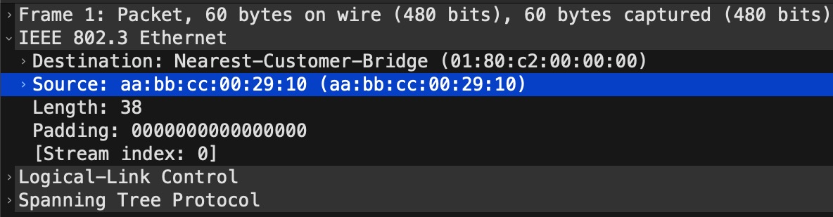
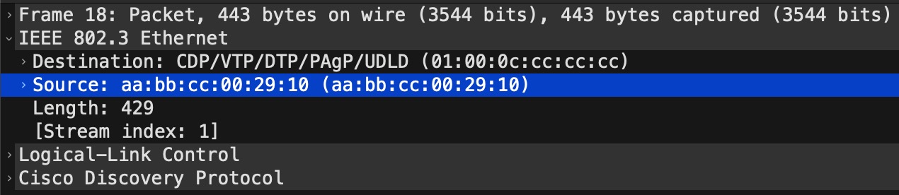
The MAC address AABBCC002910 is there because of STP (and CDP for that matter) being sent out that interface with a source MAC of the physical interface:
Switch#sh int e0/1 | in Ethernet
Ethernet0/1 is up, line protocol is up (connected)
  Hardware is Ethernet, address is aabb.cc00.2910 (bia aabb.cc00.2910)
Switch#
The STP capture to confirm this:
The CDP capture to confirm this:
So, with single-active, BGP inherently filters route type 2 from the non-DF VTEP. Hence, we have a single-active state thanks to a single bit (the “single-active” flag being set in the ESI Label).
Here is another simple way of confirming that Leaf3 only uses Leaf2 to reach our Host:
Leaf3#sh l2vpn evpn mac ip remote
IP Address                              EVI   VLAN  MAC Address    Next Hop(s)
--------------------------------------- ----- ----- -------------- -----------
10.0.123.1                              123   123   aabb.cc80.2900 100.127.1.2

Leaf3#
Next hop shows 100.127.1.2 which is Leaf2.
EVPN All-active Multihoming
With ESI multihoming or all-active, a port-channel is made between a device and two leafs. A MC-LAG using EVPN if you will.
The configuration is quite simple with a single command on the port-channel interface:
! all-active:
interface GigabitEthernet1/0/2
 description Host (Hypervisor)
 switchport access vlan 123
 channel-group 1 mode active
!
interface Port-channel1
 switchport access vlan 123
 evpn ethernet-segment auto lacp df-election wait-time 1
Without even looking at the BGP EVPN table, we can see that Leaf3 is capable of load sharing between Leaf1 and Leaf2 to reach h1, h2, and h3:
Leaf3#sh l2vpn evpn mac ip remote
IP Address                              EVI   VLAN  MAC Address    Next Hop(s)
--------------------------------------- ----- ----- -------------- -----------
10.0.123.11                             123   123   aabb.cc00.0011 100.127.1.1
                                                                   100.127.1.2
10.0.123.12                             123   123   aabb.cc00.0012 100.127.1.1
                                                                   100.127.1.2
10.0.123.13                             123   123   aabb.cc00.0013 100.127.1.1
                                                                   100.127.1.2

Leaf3#
Multihoming ESI
We saw the ESI being statically configured with single-active multihoming. But as we can see with the configuration of all-active multihoming there is an auto keyword for the ethernet-segment. All-active uses ESI type 1 where the following elements make up the ESI: (in order)
- Host LACP System MAC address (6 bytes)
- Host LACP port key (2 bytes)
- 0x00 (1 byte)
Let’s have a look at the ESI for Po1:
Leaf1#sh l2vpn evpn ethernet-segment int port-channel 1 detail
EVPN Ethernet Segment ID: 01AA.BBCC.8011.0000.0C00
  Local Discriminator:    64513
  Interface:              Po1
  Redundancy mode:        all-active
  DF election wait time:  1 seconds
  Preempt time:           N/A
  Split Horizon label:    0
  State:                  Ready
  Encapsulation:          vxlan
  Ordinal:                0
  Core Isolation:         No
  RD:                     100.127.1.1:12
    Export-RTs:           65000:123
  Forwarder List:         100.127.1.1 100.127.1.2

Leaf1#
The LACP System MAC would be AABB.CC80.1100 as the first octet (01) simply defines that the next 9 bytes (the ESI) is a type 1 ESI.
We can verify that by looking at the LACP neighbor:
Leaf1#sh lacp 1 neighbor
Flags:  S - Device is requesting Slow LACPDUs
        F - Device is requesting Fast LACPDUs
        A - Device is in Active mode       P - Device is in Passive mode

Channel group 1 neighbors

                     LACP port                      Admin  Oper   Port    Port
Port          Flags  Priority  Dev ID          Age  key    Key    Number  State
Gi1/0/2       SA     32768     aabb.cc80.1100  25s  0x0    0xC    0x2     0x3D
Leaf1#
Here it is called the Dev ID which is short for device ID.
The next value, the LACP port key, is called Oper Key in the above outout. It has a value of 0xC which is 12 in decimal. This number comes from the port-channel ID configured on the Host (hypervisor) which in my case is just a switch with the below configuration:
interface Ethernet0/1
 switchport access vlan 123
 channel-group 12 mode active
!
interface Ethernet0/2
 switchport access vlan 123
 channel-group 12 mode active
!
interface Port-channel12
 switchport access vlan 123
And lastly the remaining 0x0 or 00.
DF Election
With all-active multihoming only the DF is forwarding BUM traffic to the Host. The non-DF will block BUM traffic from being sent downstream thereby avoiding forwarding loops. Remember STP does not run on the ES.
If we look at Leaf2’s ES information for the port-channel interface:
Leaf2#sh l2vpn evpn ethernet-segment int port-channel 1 detail
EVPN Ethernet Segment ID: 01AA.BBCC.8011.0000.0C00
  Local Discriminator:    64513
  Interface:              Po1
  Redundancy mode:        all-active
  DF election wait time:  1 seconds
  Preempt time:           N/A
  Split Horizon label:    0
  State:                  Ready
  Encapsulation:          vxlan
  Ordinal:                1
  Core Isolation:         No
  RD:                     100.127.1.2:9
    Export-RTs:           65000:123
  Forwarder List:         100.127.1.1 100.127.1.2

Leaf2#
… we see that it is running in all-active redundancy mode. It knows that from the route type 1 (EAD) ES BGP update. A bit further down is an Ordinal value. This is used to determine which VTEP is elected DF for the ES. Leaf2 has ordinal 1 and Leaf1 has ordinal 0. This ordinal value is determined by looking at the route type 4 (Ethernet Segment route). All VTEPs configured for multihoming sends out a route type 4 update per ES. With the originators of these BGP updates a numerically sorted list is built using the lowest IP as the first entry. Now, the ordinal value of 0 is assigned to the first IP on the list. Ordinal 1 is assigned to the next and so on. In this case:
- Ordinal 0: 100.127.1.1
- Ordinal 1: 100.127.1.2
Next, a simple modulo function determines the DF like this:
DF (ordinal) = VLAN mod Number_of_VTEPs
In our case this boils down to this:
DF (ordinal) = 123 mod 2 = 1
Since Leaf2 was given the ordinal 1 it wins the DF election and is now DF for that ES (VLAN):
Leaf2#sh l2vpn evpn evi 123 detail | in DF
      Port-channel1 service instance 123 (DF state: forwarding)
Leaf2#
This function of load sharing which VTEP becomes the DF is also called “service carving”.
Conclusion
In this post we covered EVPN multihoming using both single-active and all-active variants. First, we looked at the theory behind ESI, ethernet tag, and EVPN route types. ESI type 0 is for single-homed and single-active connections and ESI type 1 is for all-active redundancy. An ether tag id is just a VLAN and with Cisco’s implementation where a VLAN maps to an EVI, the ethernet tag id is always set to 0 (zero). The four EVPN route types were explained. Route type 1 or EAD route has two variants. The per EVI and the per ES routes. Per-EVI is used for aliasing where a VTEP that does not receive traffic (thereby not learning about any hosts connected to it) can still attract traffic by letting other VTEPs know is has a connection to that ES. And the per ES is used for fast convergence and split horizon.
Next, single-active was demonstrated. Here we saw both the configuration and how the VTEP adds route type 2 when learning about hosts it has connected to it. We also found out that only the DF for the ES will generate route type 2 which essentially is what makes the implementation single-active by inherently filtering out route type 2 BGP update on the non-DF.
Finally, we looked at the all-active mode that uses a MC-LAG (port-channel) on two VTEPs towards a host. Here, we looked at the configuration which is just a single command under the port-channel inteface. Then we verified that both VTEPs was in fact capable of forwarding to the hosts behind them from a remote VTEP, Leaf3, that showed both Leaf1 and Leaf2 as next hops to reach h1, h2, and h3. Then we looked at the multihoming ESI generated by a VTEP. This is an ESI type 1 value made up of the LACP system MAC, the port key, and 0 (zero) for the last byte. Lastly, the DF election process was shown using the formula for calculating which VTEP is elected DF for a particular ES (VLAN). The result is DF load sharing between the VTEPs which is also known as service carving.
Thanks for reading.