EVPN on Catalyst - Layer 3
Table of Contents
For decades we’ve used MPLS layer 3 VPNs for building overlays in the enterprise networks. Although MPLS layer 3 VPN is a proven technology it lacks important security features that are requested of todays networks. Also, building layer 2 overlays using MPLS never scaled and worked best for P2P connections with no involvement of a control plane. EVPN addresses both these shortcomings of MPLS services and this post focusses on the workings of an EVPN layer 3 service using a simple example. For this the below topology has been built.
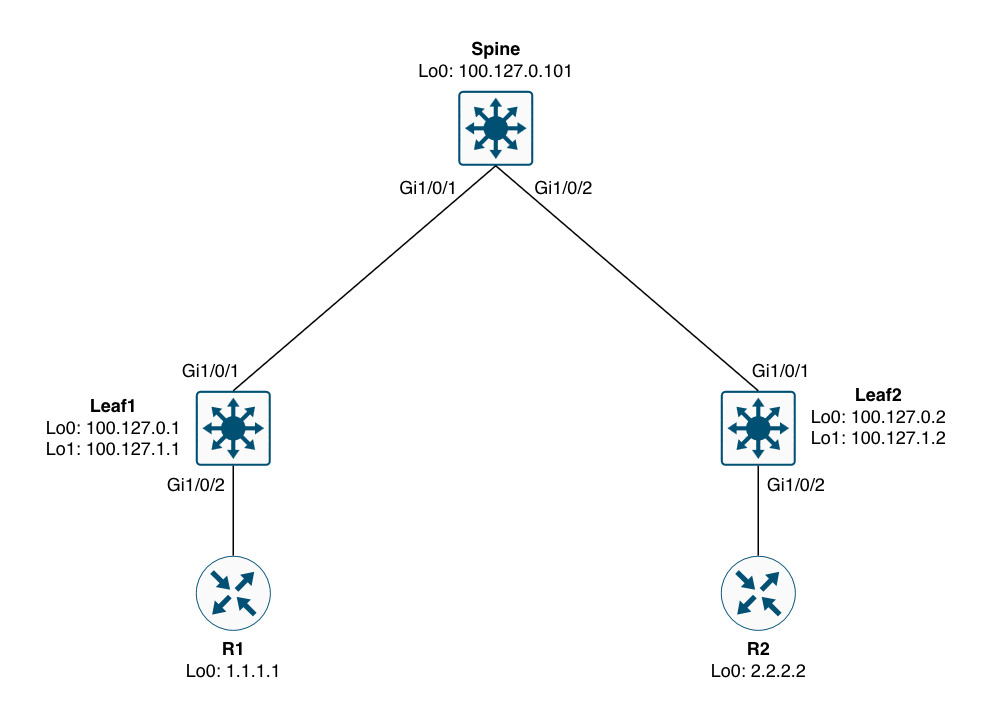
Often times we address the roles of the nodes in an EVPN network as “spine” and “leaf”. These terms come from data center networks using a scalable and high performing topology called CLOS - aka CLOS fabric. In the context of an enterprise network and in relation to MPLS you can consider the spine as the equivalent to an MPLS P node. This role does not engage in the overlay service and is used strictly in the underlay to provide reachability to the leafs (or PE nodes to compare to MPLS VPN terminology).
With EVPN the underlay is much simpler than dealing with MPLS where we also need labels to be known for the transit of packets. EVPN only requires IGP reachability in the core of the network (leaf-spine-leaf). This means that the service operates at another layer - the transport layer. Here we find VXLAN which is a UDP-based encapsulation technology that embeds our segment (VNI) along with an optional “group policy” which is part of the security feature I mentioned previously. Before we move on, let’s have a look at what this might look like in a packet capture:
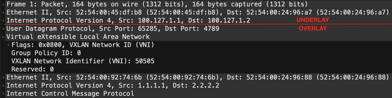
This is just a regular IP packet that contains a UDP payload which is VXLAN. The outer header (“UNDERLAY”) consists of the L2 header which gets the packet from one hop to the other (node-to-node) in transit, while the L3 header shows the leaf that originated the packet and the leaf that the packet is sent to. The “OVERLAY” part contains the VXLAN header which is encapsulated in UDP (port 4789). Here we see the Group Policy ID set to 0 (zero) and the VNI set to 50505. This VNI has the same meaning as a VPN label in MPLS VPN. With a layer 3 service, this directly maps to the VRF (or VN in today’s terminology).
Next we’ll have a look at how you implement EVPN layer 3 on Catalyst.
Configuration
Although EVPN might seem simpler than MPLS VPN in terms of the underlay, actually getting it up and running is another story. In addition to configuring a VRF, there are several overlay configuration components that can be confusing. Here is a sample configuration for the overlay part of EVPN layer 3:
! Leaf1
vrf definition test
 rd 100.127.0.1:50505
 !
 address-family ipv4
  route-target export 65000:50505
  route-target import 65000:50505
  route-target export 65000:50505 stitching
  route-target import 65000:50505 stitching
 exit-address-family
!
vlan configuration 505
 member vni 50505
!
interface Vlan505
 vrf forwarding test
 ip unnumbered Loopback1
 no autostate
!
interface nve1
 source-interface Loopback1
 host-reachability protocol bgp
 member vni 50505 vrf test
!
router bgp 65000
 no bgp default ipv4-unicast
 neighbor 100.127.0.101 remote-as 65000
 neighbor 100.127.0.101 description Spine_(RR)
 neighbor 100.127.0.101 update-source Loopback0
 !
 address-family l2vpn evpn
  neighbor 100.127.0.101 activate
  neighbor 100.127.0.101 send-community both
 exit-address-family
  !
 address-family ipv4 vrf test
  advertise l2vpn evpn
  neighbor 10.0.1.1 remote-as 65001
  neighbor 10.0.1.1 activate
 exit-address-family
EVPN Stitching Route-Target
Starting from the top with the definition of the VRF we now have two types of route-targets. The one with the “stitching” keyword is for EVPN. Without it we’re not able to import or export EVPN-bound NLRIs. In fact, this is what you’ll see if you did not configure it and an EVPN update is sent to you:
Leaf1#debug bgp l2vpn evpn updates in
Leaf1#clear bgp l2vpn evpn * in
<snip>
*Nov 24 10:00:00.954: BGP(10): 100.127.0.101 rcvd [5][100.127.0.2:3][0][32][2.2.2.2]/17 -- DENIED due to: not supported extcom for NLRI;
</snip>
Here we see 2.2.2.2/32 being DENIED because we did not configure a “stitching” import RT. Now, technically speaking, the regular route-targets (without the “stitching” keyword) are only needed if you also have MPLS VPNs configuring on the node. In this case we peer with a router (R1) from Leaf1 in a VRF (this is VRF-lite), but we do not peer with any nodes using VPNv4 (used for MPLS VPN). Hence, we can omit the regular RTs, but Cisco will show you both and not explain their usage. I hope this explains it for you. A better keyword would have been “evpn” instead of “stitching” if you ask me.
EVPN Core VLAN
Next, we see a VLAN configuration followed by an SVI for that VLAN. This is called a “CORE” VLAN and its purpose is to give the leaf a “Router MAC” address which is used to build the inner L2 header of the VXLAN packet. If we take a look at the VXLAN portion of the capture from above:
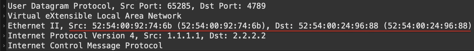
You will see a source and destination MAC address. Now you know why VXLAN is sometimes referred to as “MAC-in-UDP”. These MAC addresses must come from somewhere. This is where the SVI comes in to play. Let me show you the Vlan505 SVI on Leaf1:
Leaf1#sh interfaces vlan 505 | in Vlan|Hardware
Vlan505 is up, line protocol is up , Autostate Disabled
  Hardware is Ethernet SVI, address is 5254.0092.746b (bia 5254.0092.746b)
Leaf1#
This MAC address is what’s used as the source MAC in the inner layer 2 header of the VXLAN packet. Likewise the destination MAC address is taken from Leaf2’s core SVI. So, how did Leaf1 know which destination MAC address to use? This is signalled as the “rmac” in BGP EVPN:
Leaf1#show bgp l2vpn evpn 2.2.2.2/32
BGP routing table entry for [5][100.127.0.2:3][0][32][2.2.2.2]/17, version 46
Paths: (1 available, best #1, table EVPN-BGP-Table)
  Not advertised to any peer
  Refresh Epoch 5
  65002
    100.127.1.2 (metric 20) (via default) from 100.127.0.101 (100.127.0.101)
      Origin IGP, metric 0, localpref 100, valid, internal, best
      EVPN ESI: 00000000000000000000, Gateway Address: 0.0.0.0, VNI Label 50505, MPLS VPN Label 0
      Extended Community: RT:65000:50505 ENCAP:8 Router MAC:5254.0024.9688
      Originator: 100.127.0.2, Cluster list: 100.127.0.101
      rx pathid: 0, tx pathid: 0x0
      Updated on Nov 24 2025 10:36:41 UTC
Leaf1#
Here we see the Router MAC:5254.0024.9688 and if we look at Leaf2’s core SVI:
Leaf2#sh int vlan 505 | in Vlan|Hardware
Vlan505 is up, line protocol is up , Autostate Disabled
  Hardware is Ethernet SVI, address is 5254.0024.9688 (bia 5254.0024.9688)
Leaf2#
… the MAC is indeed that.
You might have noticed the no autostate configuration on the SVI and the Autostate Disabled state from above output. This is a safeguard for ensuring that the SVI is alway up. Normally, when you have no switchports active in a VLAN (access or trunk), the SVI goes down. Because the SVI is used for signalling and building the packets we need this to stay up at all times.
Each VRF (VN) must have its own core VLAN and SVI. And the core VLAN is configured to be a member of the VNI used for the VRF.
NVE Interface
The NVE (Network Virtualization Edge) interface is the logical interface that brings it all together and is responsible for the encapsulation/decapsulation of VLXLAN traffic (VTEP function). Here we see that the VNI is defined as a member of the interface for vrf test in our example.
It is worth mentioning that the NVE interface is configured for jumbo MTU as the VXLAN header adds 50 bytes to the packet. Therefore, like with MPLS VPNs, you must ensure to configure the underlay with an MTU value that can support the extra data.
Leaf1#sh int nve1 | in MTU|Encap
  MTU 9216 bytes, BW 1000000 Kbit/sec, DLY 10 usec,
  Encapsulation VXLAN, loopback not set
Leaf1#
The IP address of the NVE interface is unnumbered to Loopback1. It is considered best practice to use two Loopback interfaces with EVPN/VXLAN:
- Loopback0 - Used for control plane (underlay), meaning BGP EVPN. Also, typically used for managing the node
- Loopback1 - Used for data plane (overlay), meaning VXLAN encapsulation/decapsulation
Having this separation allows us to gracefully take out a node out of service by shutting down the Loopback1 interface. And clear separation of underlay and overlay is generally a good idea for troubleshooting and understanding the different parts of this technology.
Behind the scenes, the node actually creates a Tunnel interface for the handling of VXLAN traffic:
Leaf1#sh derived-config int tun0
Building configuration...

Derived configuration : 129 bytes
!
interface Tunnel0
 ip unnumbered Loopback1
 no ip redirects
 ip mtu 9216
 tunnel source 100.127.1.1
 tunnel src-port 4789
end

Leaf1#
BGP EVPN
The BGP configuration is very similar to MPLS VPN. Only the AFI/SAFI (l2vpn evpn) differs. For some reason Cisco has chosen to use “both” community types (standard and extended) to be sent for the BGP EVPN peer which technically is not needed. You can use just extended community, though, arguably no hurt is done using both.
You might wonder why the AFI is called “l2vpn” when we are dealing with layer 3 in this example. Well, EVPN was originally designed for layer 2. Later support for layer 3 (using route-type 5) was added in a separate RFC.
If you want to look at the prefixes in the VRF, you still must use the VPNv4 AFI which is kind of confusing.
Leaf1#sh bgp vpnv4 unicast vrf test | be ^$

     Network          Next Hop            Metric LocPrf Weight Path
Route Distinguisher: 100.127.0.1:50505 (default for vrf test)
AF-Private Import to Address-Family: L2VPN E-VPN, Pfx Count/Limit: 1/1000
 *>   1.1.1.1/32       10.0.1.1                 0             0 65001 i
 *>i  2.2.2.2/32       100.127.1.2              0    100      0 65002 i
Leaf1#
Here we see two prefixes. The first, “1.1.1.1/32”, is received from “10.0.1.1” which is R1. And we see “2.2.2.2/32” which is received from Leaf2 due to the import of the stitching RT. Now, to get the VRF prefixes learned “locally”, meaning from a VRF-peer, VPNv4 peer, or simply locally (connected), we need to tell the VRF to advertise it to evpn which is what the advertise l2vpn evpn does. Without it, “1.1.1.1/32”, would never be created in the “l2vpn evpn” table.
If we look closer at the prefix “2.2.2.2/32” as seen on Leaf1:
Leaf1#sh bgp l2vpn evpn 2.2.2.2/32
BGP routing table entry for [5][100.127.0.2:3][0][32][2.2.2.2]/17, version 46
Paths: (1 available, best #1, table EVPN-BGP-Table)
  Not advertised to any peer
  Refresh Epoch 5
  65002
    100.127.1.2 (metric 20) (via default) from 100.127.0.101 (100.127.0.101)
      Origin IGP, metric 0, localpref 100, valid, internal, best
      EVPN ESI: 00000000000000000000, Gateway Address: 0.0.0.0, VNI Label 50505, MPLS VPN Label 0
      Extended Community: RT:65000:50505 ENCAP:8 Router MAC:5254.0024.9688
      Originator: 100.127.0.2, Cluster list: 100.127.0.101
      rx pathid: 0, tx pathid: 0x0
      Updated on Nov 24 2025 10:36:41 UTC
Leaf1#
… we see this (most important) info:
| Type | Value | Description |
|---|---|---|
| Table | EVPN-BGP-Table | The global L2VPN EVPN BGP table that holds all EVPN NLRIs (similar to VPNv4 BGP table) |
| BGP AS | 65002 | The AS_PATH for this NLRI. In this case 2.2.2.2/32 originated in AS 65002 (R2) |
| Next hop | 100.127.1.2 | Loopback1 of Leaf2 |
| from | 100.127.0.101 | The BGP speaker that told us about this NLRI and its (router id) |
| EVPN ESI | 00000000000000000000 | Ethernet Segment Identifier is used for EVPN multi-homing. Set to zero in this case, because we have a single link to R2. |
| VNI Label | 50505 | The (layer 3) VNI we defined for VRF test |
| Extended Community | RT:65000:50505 | The Route Target associated with this prefix. Import RT must match for the prefix to be imported into the VRF. |
| ENCAP | 8 | VXLAN Encapsulation per IANA’s “Border Gateway Protocol (BGP) Tunnel Encapsulation” |
NOTE! Although we peer with EVPN using Loopback0, the NEXT_HOP attribute is actually that of the NVE interface (Loopback1). Be sure to have IP reachability to both these Loopbacks throughout your EVPN/VXLAN fabric.
Simplified EVPN Configuration
For Catalyst Cisco has implemented a shortcut in configurating VXLAN which saves you the trouble of configuring RD, RTs, and core VLAN + SVI:
vrf rd-auto
!
vrf definition test
 vnid 50505 evpn-instance vni auto core-vlan 505
 !
 address-family ipv4
 exit-address-family
!
interface nve1
 source-interface Loopback1
 host-reachability protocol bgp
 member vni 50505 vrf test
!
router bgp 65000
 no bgp default ipv4-unicast
 neighbor 100.127.0.101 remote-as 65000
 neighbor 100.127.0.101 description Spine_(RR)
 neighbor 100.127.0.101 update-source Loopback0
 !
 address-family l2vpn evpn
  neighbor 100.127.0.101 activate
  neighbor 100.127.0.101 send-community both
 exit-address-family
  !
 address-family ipv4 vrf test
  advertise l2vpn evpn
  neighbor 10.0.1.1 remote-as 65001
  neighbor 10.0.1.1 activate
 exit-address-family
Here, the vnid and core vlan id is configured under the VRF. This function requires the rd to be set to auto.
With this the RD, RTs, core VLAN, and SVI will be a runtime state and not present in the running configuration.
NOTE! The syntax of using this configuration shortcut might different depending on the platform and/or software version you’re using.
Regarding the auto RD feature, be aware that migrating from RD auto to manual RD configuration causes BGP to DELETE your VRF BGP peerings and you must wait till the RD has been deleted before you can configure one yourself. This takes some time:
Leaf1(config)#no vrf rd-auto
*Nov 24 09:41:36.798: %BGP_SESSION-5-ADJCHANGE: neighbor 10.0.1.1 IPv4 Unicast vpn vrf test topology base removed from session  Neighbor deleted
*Nov 24 09:41:36.798: %BGP-5-ADJCHANGE: neighbor 10.0.1.1 vpn vrf test Down Neighbor deleted
Leaf1(config)#vrf definition test
Leaf1(config-vrf)#rd 100.127.0.1:50505
% Deletion of RD in progress; wait for it to complete
Leaf1(config-vrf)#
Unfortunately, you cannot configure the RD manually when auto RD is in effect, making migrating away from auto RD hitfull (you’ll need a maintenance window as this causes service disruption):
Leaf1(config-vrf)#rd 100.127.0.1:50505
% Static RDs are not allowed when rd auto is configured. Disable rd auto first.
NOTE! You can configure static RD for non-EVPN VRFs.
EVPN Verification and Troubleshooting
Besides looking at the BGP table, you can do a NVE peers verification:
Leaf1#sh nve peers vni 50505
'M' - MAC entry download flag  'A' - Adjacency download flag
'4' - IPv4 flag  '6' - IPv6 flag

Interface  VNI      Type Peer-IP          RMAC/Num_RTs   eVNI     state flags UP time
nve1       50505    L3CP 100.127.1.2      5254.0024.9688 50505      UP  A/M/4 00:30:57
Leaf1#
Seeing a peer for the VNI in an “UP” state is an indication that things are configured correctly and the network should be in a working state.
If you do not see an NVE peer, but you see the NLRIs in the l2vpn evpn BGP table, it might be because the NVE interface is down on the peer. Here are the outputs of when the NVE interface is down and when it is up for a prefix:
NVE interface down:
Leaf1#sh bgp l2vpn evpn 2.2.2.2/32
BGP routing table entry for [5][100.127.0.2:3][0][32][2.2.2.2]/17, version 46
Paths: (1 available, best #1, table EVPN-BGP-Table)
  Not advertised to any peer
  Refresh Epoch 3
  65002
    100.127.0.2 (metric 20) (via default) from 100.127.0.101 (100.127.0.101)
      Origin IGP, metric 0, localpref 100, valid, internal, best
      EVPN ESI: 00000000000000000000, Gateway Address: 0.0.0.0, VNI Label 0, MPLS VPN Label 16
      Extended Community: RT:65000:50505
      Originator: 100.127.0.2, Cluster list: 100.127.0.101
      rx pathid: 0, tx pathid: 0x0
      Updated on Nov 24 2025 12:26:53 UTC
Leaf1#
NVE interface up:
Leaf1#sh bgp l2vpn evpn 2.2.2.2/32
BGP routing table entry for [5][100.127.0.2:3][0][32][2.2.2.2]/17, version 47
Paths: (1 available, best #1, table EVPN-BGP-Table)
  Not advertised to any peer
  Refresh Epoch 3
  65002
    100.127.1.2 (metric 20) (via default) from 100.127.0.101 (100.127.0.101)
      Origin IGP, metric 0, localpref 100, valid, internal, best
      EVPN ESI: 00000000000000000000, Gateway Address: 0.0.0.0, VNI Label 50505, MPLS VPN Label 0
      Extended Community: RT:65000:50505 ENCAP:8 Router MAC:5254.0024.9688
      Originator: 100.127.0.2, Cluster list: 100.127.0.101
      rx pathid: 0, tx pathid: 0x0
      Updated on Nov 24 2025 12:28:53 UTC
Leaf1#
Notice these things change:
- VNI Label is 0 instead of our VNI
- MPLS VPN Label is non-zero (16)
- ENCAP:8 is gone
- Router MAC is gone
Other reasons why you don’t see the peer relates to the underlay. Reachability to the Loopback interfaces of your peer(s) must be present.
Ensure the overlay (BGP) is working.
If everything looks good but traffic is dropped, be sure to check MTU size in the underlay.
And as always, be structured. Check the configuration meticulously to ensure you didn’t forget something.
Conclusion
BGP EVPN with VXLAN has come to stay. It is not that different from MPLS VPNs and gives us extra security features with the group policy option. Transport between ingress and egress VTEPs relies only on IP reachability with the segmentation information moved to the transport layer of the packets. With the added information, the VXLAN header, it is important to have a proper MTU, because VXLAN adds 50 bytes to the data.
Stitching route targets was explained and unless you are doing some interworking between MPLS VPNs and EVPN you do not need regular route targets. The stitching RT is required for EVPN only. And in BGP you must instruct the node to advertise VRF-learned routes to EVPN in order to export them and use them in EVPN.
The core VLAN and SVI are essential with layer 3 VNI as the MAC address of the SVI is used to build inner layer 2 header in the packet.
Configuration of EVPN with VXLAN can be cumbersome, but configuration shortcuts are available.
Although BGP peers using the Loopback0 IP, the NEXT_HOP and data plane uses Loopback1. Having both gives a clear separation of underlay and overlay which is considered a best practice.
Troubleshooting can be difficult, but a show of NVE peers in the up state indicates that things should work. If not, you’ll need to do regular troubleshooting to verify the underlay and overlay - in that order.