EVPN on Catalyst - Layer 2
Table of Contents
Fabric-based networks are no longer exclusive to the data center or service provider networks. Today we use fabric-based networks all over to provide the network services needed to support our business. I like to define a fabric-based network by two things:
- A network of devices (typically switches) that optimally inter-connect in a strict uniform way (think physical topology here)
- A robust network built to support L2 and L3 services on top of it using the concepts of underlay and overlays
Roughly speaking the underlay is nothing but a L3 network responsible for providing reachability between the devices that hold our endpoints (be they users or servers). The overlay(s) on the other hand consist of the payload of the endpoints which is tunneled (encapsulated) between the devices that hold the endpoints. When we speak of “network services” we’re commonly referring to the overlays of our network. And as you might have figured out by now, all these fancy words are just ways we address and talk about network virtualization.
With a bit of background info let’s dive into EVPN as a fabric-based network. Specifically, this post focusses on the campus network, hence I use Catalyst (IOS XE) software to walk you through the technology - here at Layer 2.
EVPN Topology and Building Blocks
To keep things as simple as possible the network below consists of just three nodes and two hosts.
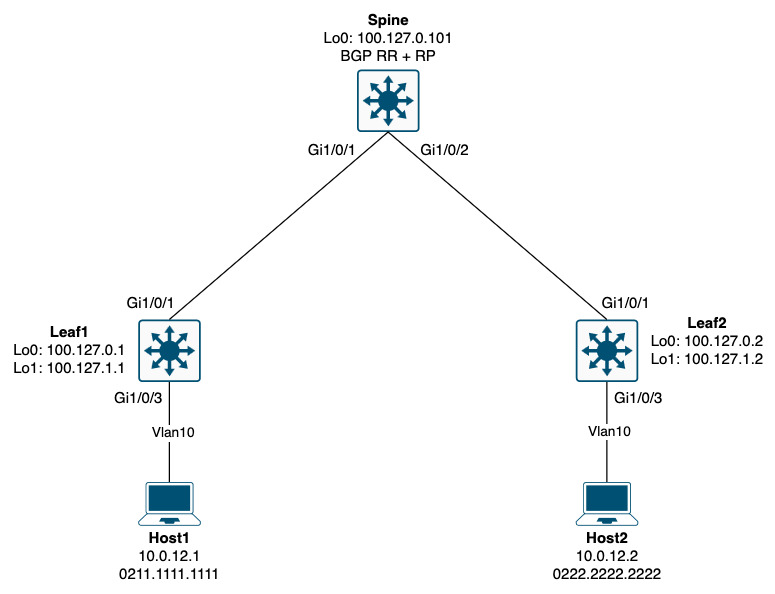
Node terminology:
| Name | Definition |
|---|---|
| Spine | An intermediate node that does not connect to endpoints. It sits in the underlay providing reachability between leaf nodes as well as a central distribution point for control plane information for our overlay services. For this it holds the BGP RR role and also serves as RP for multicast in the underlay. |
| Leaf | A node to which endpoints connect. It advertises and receives endpoint reachability information to/from the spine and is responsible for encapsulating and decapsulating the data that needs to be sent between endpoints connected to different leaf nodes. |
The two hosts (Host1 and Host2) are connected to Vlan10 and share the subnet 10.0.12.0/24. In a traditional network for these two hosts to communicate we’d use L2 directly between the switches. Each switch would then learn about the MAC addresses of the two hosts as they start communicating with each other. This is called data plane learning. For this to work, each switch floods the traffic when the destination MAC address has not been learned yet. It is inefficient and does not scale. This is where EVPN shines as BGP now handles the signalling of the reachability information (MAC addresses).
Since we just learned that an underlay is built using L3, we need a way to bridge the data between the two hosts. We need an overlay - a tunnel/an encapsulation. This could be MPLS, but in most cases and especially for enterprise-based networks, this is typically VXLAN. Now, VXLAN is nothing but a UDP encapsulation wrapped around the frames sent by our hosts. It uses the well-known (fixed) destination port of 4789.

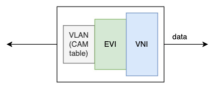
At ingress when Host1, for example, sends traffic, Leaf1 learns about the MAC address of Host1. This is still data plane learning. Leaf1 keeps this information in a per-VLAN CAM table (MAC address table). For EVPN, since we’re virtualizing the network, we need a VRF to hold this information - just like we do with IP-VRFs. With EVPN, we just call this a MAC-VRF as it holds L2 ethernet information (MAC addresses) instead of L3 information (IP addresses). Now, in theory a MAC-VRF can hold multiple broadcast domains (VLANs), but with Cisco’s implementation there is a 1:1 mapping between a VLAN and a MAC-VRF. And in fact, when it comes to EVPN this MAC-VRF is called an EVI - EVPN Instance (some might say “Ethernet Virtual Instance”). The final piece of information needed is a “label” for the VXLAN header. This binds the packet to the EVI, letting the receiving node (Leaf2 in the current example) know where (which EVI) it should look. This is no different from the label to VRF mapping seen with MPLS L3 VPNs (if you have per-VRF label allocation configured). With VXLAN this “label” is called VNI (Virtual Network Identifier).
A node that encapsulates/decapsulates VXLAN traffic is called a VTEP (Virtual Tunnel Endpoint).
I’ve tried to visualize this:
To sum up:
| Name | Definition |
|---|---|
| EVI | EVPN Instance (MAC-VRF) that holds information for a VLAN |
| VNI | Virtual Network Identifier (sometimes called VXLAN Network Identifier) is a “label” used in the VXLAN header to identify the EVI for the packet |
| VTEP | Virtual Tunnel Endpoint. A node that does VXLAN encap/decap. |
EVPN Layer 2 Configuration
Leaf1 and Leaf2 are configured the same, so let’s just have a look a one of them - Leaf1:
! Leaf1 EPVN Layer 2 Configuration:

ip routing
ip multicast-routing
!
vlan 10
 name EVPN
!
l2vpn evpn
 replication-type static
 router-id Loopback1
!
l2vpn evpn instance 101 vlan-based
 encapsulation vxlan
!
vlan configuration 10
 member evpn-instance 101 vni 10101
!
interface nve1
 no ip address
 source-interface Loopback1
 host-reachability protocol bgp
 member vni 10101 mcast-group 225.0.0.101
!
interface Loopback0
 description ROUTING (CONTROL PLANE)
 ip address 100.127.0.1 255.255.255.255
!
interface Loopback1
 description VXLAN (DATA PLANE)
 ip address 100.127.1.1 255.255.255.255
 ip pim sparse-mode
!
interface GigabitEthernet1/0/1
 description Spine
 no switchport
 ip address 100.64.1.1 255.255.255.254
 ip pim sparse-mode
 ip router isis 1
 isis network point-to-point
!
router isis 1
 net 49.1001.2700.0001.00
 is-type level-2-only
 advertise passive-only
 metric-style wide
 max-lsp-lifetime 65535
 lsp-refresh-interval 65000
 spf-interval 5 1 20
 prc-interval 5 1 20
 lsp-gen-interval 5 1 20
 no hello padding point-to-point
 passive-interface Loopback0
 passive-interface Loopback1
!
ip pim rp-address 100.127.255.255
!
router bgp 65000
 bgp router-id interface Loopback0
 bgp log-neighbor-changes
 no bgp default ipv4-unicast
 neighbor 100.127.0.101 remote-as 65000
 neighbor 100.127.0.101 update-source Loopback0
 !
 address-family l2vpn evpn
  neighbor 100.127.0.101 activate
  neighbor 100.127.0.101 send-community extended
 exit-address-family
!
interface GigabitEthernet1/0/3
 description Host1
 switchport access vlan 10
 switchport mode access
 spanning-tree portfast
VLAN 10 is created. This will create a CAM table for VLAN 10 along with an STP instance. Now we have a place to put MAC addresses learned in that VLAN. Then EVPN is configured globally with a router ID of our VXLAN data plane loopback, Lo1, and replication set to static, meaning we define a multicast group statically for BUM traffic. As an alternative you can configure “ingress” as the replication type which will create a copy of the packet for each VTEP and use unicast for forwarding the traffic that needs flooding. Each VTEP will signal this with a BGP update using an EVPN Route Type 3 (Inclusive Multicast Ethernet Tag Route). Using ingress replication is inefficient, hence I recommand to go with using multicast replication with the “static” approach when possible. You can mix the two types and have some EVIs using static and others using ingress. Next, the EVI is created and configured to use VXLAN as the encapsulation. The final step is to bind the EVI to the VLAN. This is done using the vlan configuration mode where we tell it to be a member of the newly configured EVI and to use the VNI as the “label” when creating the VXLAN header. Lastly, a NVE (Network Virtualization Endpoint) interface has been created to define this node as a VTEP. Here, the multicast group for the VNI is defined along with a source interface (lo1) and a statement that tells the node to use BGP for host reachability.
The rest is basic routing and I will not go into detail as this post’s focus is on EVPN.
Spine - EVPN Configuration:

ip routing
ip multicast-routing
!
interface Loopback0
 description ROUTING (CONTROL PLANE)
 ip address 100.127.0.101 255.255.255.255
!
interface Loopback255
 description Anycast RP
 ip address 100.127.255.255 255.255.255.255
 ip pim sparse-mode
!
interface GigabitEthernet1/0/1
 description Leaf1
 no switchport
 ip address 100.64.1.0 255.255.255.254
 ip pim sparse-mode
 ip router isis 1
 isis network point-to-point
!
interface GigabitEthernet1/0/2
 description Leaf2
 no switchport
 ip address 100.64.2.0 255.255.255.254
 ip pim sparse-mode
 ip router isis 1
 isis network point-to-point
!
ip pim rp-address 100.127.255.255
!
router isis 1
 net 49.1001.2700.0101.00
 is-type level-2-only
 advertise passive-only
 metric-style wide
 max-lsp-lifetime 65535
 lsp-refresh-interval 65000
 spf-interval 5 1 20
 prc-interval 5 1 20
 lsp-gen-interval 5 1 20
 no hello padding point-to-point
 passive-interface Loopback0
 passive-interface Loopback255
!
router bgp 65000
 template peer-policy peer_policy
  route-reflector-client
 exit-peer-policy
 !
 template peer-session peer_session
  remote-as 65000
  update-source Loopback0
 exit-peer-session
 !
 bgp router-id interface Loopback0
 bgp log-neighbor-changes
 no bgp default ipv4-unicast
 neighbor 100.127.0.1 inherit peer-session peer_session
 neighbor 100.127.0.2 inherit peer-session peer_session
 !
 address-family l2vpn evpn
  neighbor 100.127.0.1 activate
  neighbor 100.127.0.1 send-community extended
  neighbor 100.127.0.1 inherit peer-policy peer_policy
  neighbor 100.127.0.2 activate
  neighbor 100.127.0.2 send-community extended
  neighbor 100.127.0.2 inherit peer-policy peer_policy
 exit-address-family
For the Spine there is very little stuff that relates to EVPN except for BGP. I will elaborate a bit on how BGP makes all of this work later… NOTE that the spine has been configured as rendezvous point (RP) as EVPN uses ASM.
EVPN Operation
With a brief introduction and some configuration we should be ready to start diving into how it all works. Refer to the topology when looking at the outputs in this seciton.
Endpoint Learning
An endpoint will send out an ARP probe when it brings up its NIC. This is to detect duplicate IP address on the network:
Leaf1#sh mon cap file flash:host1.pcap display-filter frame.number==12 detail | be ^Ethernet II
Ethernet II, Src: 02:11:11:11:11:11 (02:11:11:11:11:11), Dst: ff:ff:ff:ff:ff:ff (ff:ff:ff:ff:ff:ff)
    Destination: ff:ff:ff:ff:ff:ff (ff:ff:ff:ff:ff:ff)
        Address: ff:ff:ff:ff:ff:ff (ff:ff:ff:ff:ff:ff)
        .... ..1. .... .... .... .... = LG bit: Locally administered address (this is NOT the factory default)
        .... ...1 .... .... .... .... = IG bit: Group address (multicast/broadcast)
    Source: 02:11:11:11:11:11 (02:11:11:11:11:11)
        Address: 02:11:11:11:11:11 (02:11:11:11:11:11)
        .... ..1. .... .... .... .... = LG bit: Locally administered address (this is NOT the factory default)
        .... ...0 .... .... .... .... = IG bit: Individual address (unicast)
    Type: ARP (0x0806)
    Padding: 000000000000000000000000000000000000
Address Resolution Protocol (reply/gratuitous ARP)
    Hardware type: Ethernet (1)
    Protocol type: IPv4 (0x0800)
    Hardware size: 6
    Protocol size: 4
    Opcode: reply (2)
    [Is gratuitous: True]
    Sender MAC address: 02:11:11:11:11:11 (02:11:11:11:11:11)
    Sender IP address: 10.0.12.1
    Target MAC address: ff:ff:ff:ff:ff:ff (ff:ff:ff:ff:ff:ff)
    Target IP address: 10.0.12.1
This broadcast is seen on Leaf1 and the source MAC is learned along with the IP address of Host1:
Leaf1#sh device-tracking database int gi1/0/3 | be _Network Layer
    Network Layer Address                    Link Layer Address     Interface  vlan       prlvl      age        state      Time left
ARP 10.0.12.1                                0211.1111.1111         Gi1/0/3    10         0005       3s         REACHABLE  311 s
This information is then populated into the EVPN manager:
Leaf1#sh l2vpn evpn mac ip vlan 10 detail
IP Address:                10.0.12.1
EVPN Instance:             101
Vlan:                      10
MAC Address:               0211.1111.1111
Ethernet Segment:          0000.0000.0000.0000.0000
Ethernet Tag ID:           0
Next Hop(s):               V:10101 GigabitEthernet1/0/3 service instance 10
Sequence Number:           0
IP Duplication Detection:  Timer not running
Label2 included:           No
Here we have all reachability information correlated (IP, MAC, EVI, VNI, Interface).
Next, the information is taken to the L2RIB:
Leaf1#show l2route evpn mac ip mac-address 0211.1111.1111 detail
EVPN Instance:            101
Ethernet Tag:             0
Producer Name:            L2VPN
MAC Address:              0211.1111.1111
Host IP:                  10.0.12.1
Sequence Number:          0
Label 2:                  0
ESI:                      0000.0000.0000.0000.0000
MAC Route Flags:          B()
Next Hop(s):              Gi1/0/3:10
And finally a BGP entry is created:
Leaf1#sh bgp l2vpn evpn 0211.1111.1111
BGP routing table entry for [2][100.127.1.1:101][0][48][021111111111][0][*]/20, version 60
Paths: (1 available, best #1, table evi_101)
  Advertised to update-groups:
     1
  Refresh Epoch 1
  Local
    0.0.0.0 (via default) from 0.0.0.0 (100.127.0.1)
      Origin incomplete, localpref 100, weight 32768, valid, sourced, local, best
      EVPN ESI: 00000000000000000000, Label1 10101
      Extended Community: RT:65000:101 ENCAP:8
      Local irb vxlan vtep:
        vrf:not found, l3-vni:0
        local router mac:0000.0000.0000
        core-irb interface:(not found)
        vtep-ip:100.127.1.1
      rx pathid: 0, tx pathid: 0x0
      Updated on Jun 28 2025 15:00:57 UTC
BGP routing table entry for [2][100.127.1.1:101][0][48][021111111111][32][10.0.12.1]/24, version 63
Paths: (1 available, best #1, table evi_101)
  Advertised to update-groups:
     1
  Refresh Epoch 1
  Local
    0.0.0.0 (via default) from 0.0.0.0 (100.127.0.1)
      Origin incomplete, localpref 100, weight 32768, valid, sourced, local, best
      EVPN ESI: 00000000000000000000, Label1 10101
      Extended Community: RT:65000:101 ENCAP:8
      Local irb vxlan vtep:
        vrf:not found, l3-vni:0
        local router mac:0000.0000.0000
        core-irb interface:(not found)
        vtep-ip:100.127.1.1
      rx pathid: 0, tx pathid: 0x0
      Updated on Jun 28 2025 15:03:15 UTC
Leaf1#
From the top we see a “BGP routing table entry” and then a number in the brackets. This designates the BGP EVPN route type. In this case a RT 2 which is for the advertisement of MAC/IP. And we actually have two entries. One with just the MAC and one with both MAC and IP.
Next we see the table to which this entry belongs: “evi_101”
Also, notice the “Label1” which is our VNI. This was the reason why I choose to use the word “label” in the introduction of this post.
For the Extended communities we have a RT (Route Target) which is used the same way as MPLS L3 VPNs. The beautiful thing with EVPN is that you need not specify the RD and/or RTs. By default, the VTEP router-id (Lo1 in this case) is used to construct the RD along with the EVI. And the RT value consists of the BGP ASN and the EVI.
The ENCAP tells the receiving node which protocol encapsulation to use when sending traffic to us. In this case “8” which is VXLAN. For reference here are the different options for this:
rfc8365 - BGP Tunnel Encapsulation Attribute Tunnel Types
If we look at Leaf2 when it receives this update:
Leaf2#sh bgp l2vpn evpn 021111111111
BGP routing table entry for [2][100.127.1.1:101][0][48][021111111111][0][*]/20, version 74
Paths: (1 available, best #1, table EVPN-BGP-Table)
  Not advertised to any peer
  Refresh Epoch 6
  Local
    100.127.1.1 (metric 20) (via default) from 100.127.0.101 (100.127.0.101)
      Origin incomplete, metric 0, localpref 100, valid, internal, best
      EVPN ESI: 00000000000000000000, Label1 10101
      Extended Community: RT:65000:101 ENCAP:8
      Originator: 100.127.0.1, Cluster list: 100.127.0.101
      rx pathid: 0, tx pathid: 0x0
      Updated on Jun 28 2025 15:00:57 UTC
BGP routing table entry for [2][100.127.1.1:101][0][48][021111111111][32][10.0.12.1]/24, version 77
Paths: (1 available, best #1, table EVPN-BGP-Table)
  Not advertised to any peer
  Refresh Epoch 6
  Local
    100.127.1.1 (metric 20) (via default) from 100.127.0.101 (100.127.0.101)
      Origin incomplete, metric 0, localpref 100, valid, internal, best
      EVPN ESI: 00000000000000000000, Label1 10101
      Extended Community: RT:65000:101 ENCAP:8
      Originator: 100.127.0.1, Cluster list: 100.127.0.101
      rx pathid: 0, tx pathid: 0x0
      Updated on Jun 28 2025 15:03:15 UTC
BGP routing table entry for [2][100.127.1.2:101][0][48][021111111111][0][*]/20, version 75
Paths: (1 available, best #1, table evi_101)
  Not advertised to any peer
  Refresh Epoch 6
  Local, imported path from [2][100.127.1.1:101][0][48][021111111111][0][*]/20 (global)
    100.127.1.1 (metric 20) (via default) from 100.127.0.101 (100.127.0.101)
      Origin incomplete, metric 0, localpref 100, valid, internal, best
      EVPN ESI: 00000000000000000000, Label1 10101
      Extended Community: RT:65000:101 ENCAP:8
      Originator: 100.127.0.1, Cluster list: 100.127.0.101
      rx pathid: 0, tx pathid: 0x0
      Updated on Jun 28 2025 15:00:57 UTC
BGP routing table entry for [2][100.127.1.2:101][0][48][021111111111][32][10.0.12.1]/24, version 78
Paths: (1 available, best #1, table evi_101)
  Not advertised to any peer
  Refresh Epoch 6
  Local, imported path from [2][100.127.1.1:101][0][48][021111111111][32][10.0.12.1]/24 (global)
    100.127.1.1 (metric 20) (via default) from 100.127.0.101 (100.127.0.101)
      Origin incomplete, metric 0, localpref 100, valid, internal, best
      EVPN ESI: 00000000000000000000, Label1 10101
      Extended Community: RT:65000:101 ENCAP:8
      Originator: 100.127.0.1, Cluster list: 100.127.0.101
      rx pathid: 0, tx pathid: 0x0
      Updated on Jun 28 2025 15:03:15 UTC
Leaf2#
Here we have many entries. This is because like VPNv4 (MPLS L3 VPNs) we have a global table (here called “EVPN-BGP-Table”) that holds the information received from the BGP peering. From this table we import the applicable routes based on the RT found in the extended community.
If you want you can verify EVI settings and attributes here:
Leaf1#sh l2vpn evpn evi 101 detail
EVPN instance:       101 (VLAN Based)
  RD:                100.127.1.1:101 (auto)
  Import-RTs:        65000:101
  Export-RTs:        65000:101
  Per-EVI Label:     none
  State:             Established
  Replication Type:  Static (global)
  Encapsulation:     vxlan
  IP Local Learn:    Enabled (global)
  Adv. Def. Gateway: Disabled (global)
  Re-originate RT5:  Disabled
  Adv. Multicast:    Disabled (global)
  AR Flood Suppress: Enabled (global)
  Vlan:              10
    Protected:       False
    Ethernet-Tag:    0
    State:           Established
    Flood Suppress:  Attached
    Core If:
    Access If:
    NVE If:          nve1
    RMAC:            0000.0000.0000
    Core Vlan:       0
    L2 VNI:          10101
    L3 VNI:          0
    VTEP IP:         100.127.1.1
    MCAST IP:        225.0.0.101
    Pseudoports:
      GigabitEthernet1/0/3 service instance 10
        Routes: 1 MAC, 1 MAC/IP
    Peers:
      100.127.1.2
        Routes: 1 MAC, 0 MAC/IP, 0 IMET, 0 EAD
Traffic Forwarding
Before we start sending packets between Host1 and Host2, let’s look at their ARP tables:
Host1:
Host1#sh ip arp
Protocol  Address          Age (min)  Hardware Addr   Type   Interface
Internet  10.0.12.1               -   0211.1111.1111  ARPA   Ethernet0/1
Host1#
Host2:
Host2#sh ip arp
Protocol  Address          Age (min)  Hardware Addr   Type   Interface
Internet  10.0.12.2               -   0222.2222.2222  ARPA   Ethernet0/1
Host2#
Ok, so nothing has happend yet. Since they’re on the same vlan (and subnet) when we ping from Host1 to Host2, Host1 will need to send out an ARP request. Let’s look at a capture from this:
Spine#sh mon cap jz buffer brief | in ARP
    4  11.055192 02:11:11:11:11:11 -> 02:22:22:22:22:22 ARP 110 Who has 10.0.12.2? Tell 10.0.12.1
    5  11.176299 02:22:22:22:22:22 -> 02:11:11:11:11:11 ARP 110 10.0.12.2 is at 02:22:22:22:22:22
Spine#
And let’s look at the details of packet number 4 which is the ARP request from Host1 asking for the MAC address of Host2 (10.0.12.2):
Spine#sh mon cap jz buffer display-filter frame.number==4 detailed  | be ^Ethernet II
Ethernet II, Src: 52:54:00:92:74:8a (52:54:00:92:74:8a), Dst: 52:54:00:45:df:c6 (52:54:00:45:df:c6)
    Destination: 52:54:00:45:df:c6 (52:54:00:45:df:c6)
        Address: 52:54:00:45:df:c6 (52:54:00:45:df:c6)
        .... ..1. .... .... .... .... = LG bit: Locally administered address (this is NOT the factory default)
        .... ...0 .... .... .... .... = IG bit: Individual address (unicast)
    Source: 52:54:00:92:74:8a (52:54:00:92:74:8a)
        Address: 52:54:00:92:74:8a (52:54:00:92:74:8a)
        .... ..1. .... .... .... .... = LG bit: Locally administered address (this is NOT the factory default)
        .... ...0 .... .... .... .... = IG bit: Individual address (unicast)
    Type: IPv4 (0x0800)
Internet Protocol Version 4, Src: 100.127.1.1, Dst: 100.127.1.2
    0100 .... = Version: 4
    .... 0101 = Header Length: 20 bytes (5)
    Differentiated Services Field: 0x00 (DSCP: CS0, ECN: Not-ECT)
        0000 00.. = Differentiated Services Codepoint: Default (0)
        .... ..00 = Explicit Congestion Notification: Not ECN-Capable Transport (0)
    Total Length: 96
    Identification: 0x0065 (101)
    Flags: 0x40, Don't fragment
        0... .... = Reserved bit: Not set
        .1.. .... = Don't fragment: Set
        ..0. .... = More fragments: Not set
    Fragment Offset: 0
    Time to Live: 254
    Protocol: UDP (17)
    Header Checksum: 0xb126 [validation disabled]
    [Header checksum status: Unverified]
    Source Address: 100.127.1.1
    Destination Address: 100.127.1.2
User Datagram Protocol, Src Port: 65412, Dst Port: 4789
    Source Port: 65412
    Destination Port: 4789
    Length: 76
    [Checksum: [missing]]
    [Checksum Status: Not present]
    [Stream index: 0]
    [Timestamps]
        [Time since first frame: 0.000000000 seconds]
        [Time since previous frame: 0.000000000 seconds]
    UDP payload (68 bytes)
Virtual eXtensible Local Area Network
    Flags: 0x0800, VXLAN Network ID (VNI)
        0... .... .... .... = GBP Extension: Not defined
        .... .... .0.. .... = Don't Learn: False
        .... 1... .... .... = VXLAN Network ID (VNI): True
        .... .... .... 0... = Policy Applied: False
        .000 .000 0.00 .000 = Reserved(R): 0x0000
    Group Policy ID: 0
    VXLAN Network Identifier (VNI): 10101
    Reserved: 0
Ethernet II, Src: 02:11:11:11:11:11 (02:11:11:11:11:11), Dst: 02:22:22:22:22:22 (02:22:22:22:22:22)
    Destination: 02:22:22:22:22:22 (02:22:22:22:22:22)
        Address: 02:22:22:22:22:22 (02:22:22:22:22:22)
        .... ..1. .... .... .... .... = LG bit: Locally administered address (this is NOT the factory default)
        .... ...0 .... .... .... .... = IG bit: Individual address (unicast)
    Source: 02:11:11:11:11:11 (02:11:11:11:11:11)
        Address: 02:11:11:11:11:11 (02:11:11:11:11:11)
        .... ..1. .... .... .... .... = LG bit: Locally administered address (this is NOT the factory default)
        .... ...0 .... .... .... .... = IG bit: Individual address (unicast)
    Type: ARP (0x0806)
    Trailer: 000000000000000000000000000000000000
Address Resolution Protocol (request)
    Hardware type: Ethernet (1)
    Protocol type: IPv4 (0x0800)
    Hardware size: 6
    Protocol size: 4
    Opcode: request (1)
    Sender MAC address: 02:11:11:11:11:11 (02:11:11:11:11:11)
    Sender IP address: 10.0.12.1
    Target MAC address: 02:22:22:22:22:22 (02:22:22:22:22:22)
    Target IP address: 10.0.12.2


Spine#
As you can see, we start from the top with and outer Ethernet header, followed by the outer IP header, and UDP header with the destination port 4789 (VXLAN). This is all stuff we’re used to seeing in our networks (UDP applications). But notice the IP header. The DF-bit has been set. And since we encapsulates the entire frame, an issue can arrise with the size of the packet as it traverses our fabric. For this reason we need to set a proper MTU which technically can be 1550 bytes, but in a campus environment where we control the physical infrastructure, we’d typically go with 9100 bytes.
The VXLAN header contains our VNI of 10101 which is expected.
The actual ARP request has been converted into unicast! This is per RFC and an optimization used with ARP suppression where the ingress VTEP will forward the ARP request to the egress VTEP (destination) when the MAC address is known. The egress VTEP will then reply on behalf of Host2 (thereby suppressing that ARP request). This feature is On by default and can be turned off at globally or per EVI.
Conclusion
In the post we went through quite a lot of content covering EVPN Layer 2 on Catalyst. I hope you feel more confident and enlightened when it comes to EVPN and VXLAN. We talked about fabric-based networks with underlay and overlays. Then EVPN was broken down from a perspective of network virtualization looking at the CAM table, then MAC-VRF called EVI, and finally the “label” used for forward, the VNI. Both the configuration and packet captures was shown for solidify the theory we began with.
Thanks for reading.