DNAC - SDA Transit with Direct Internet Access
Table of Contents
Some companies are established with multiple sites in a small geographic area inter-connected with DWDM, dark fiber, or maybe MPLS. SDA transit could make sense to configure if the MTU (>= 1550 bytes) and latency (~10 ms) allows for it. One advantage of using SDA transit is the end-to-end VXLAN encapsulation which menas we have end-to-end policy for both macro (VN) and micro (SGT) segmentation when using SDA transit.
In this post I’ll go over how you could go about configuring direct internet access (DIA) using SDA transit. Along the way I’ll show how it works and why.
Topology and Use Case
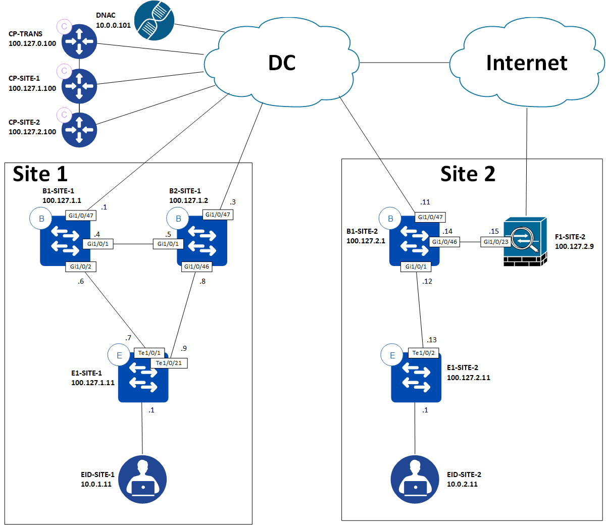
Here we have two sites. One of them, Site 2, has a need for DIA for the Users VN. Endpoints in the Users VN must also be able to reach shared services hosted centrally in the DC and other endpoints in other sites in the same VN.
Border Configuration
In this specific network we have no need for using internal borders. There is only one way to go for all non-SDA traffic - everything is backhauled to the DC block. We coule have had other network modules like a WAN block in which case internal borders might have made sense. For this network, however, we keep things simple and in small scale.
Cisco documents the border configuration options like this:
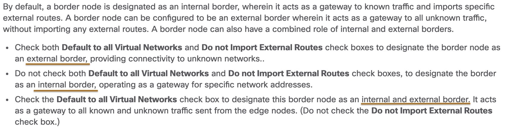
Reference: Add a Device as a Border Node
When we configure a border as an external border the following is configured in LISP on all Edge nodes for that site:
! E1-SITE-2:
router lisp
 service ipv4
  use-petr 100.127.2.1
Here the PETR (Proxy Egress Tunnel Router) of 100.127.2.1 is used as a “gateway of last resort”, meaning that in case if have a LISP lookup miss (the EID wasn’t found in the MS/Control Plane node), the packet is encapsulated with a VXLAN header and sent to 100.127.2.1 (our External border) for Site 2.
Multi-site LISP
Using SDA with SDA transit creates a two-tier hierarchical LISP network where borders are re-encapsulating tunnel routers (RTRs). Logically this may look like this:
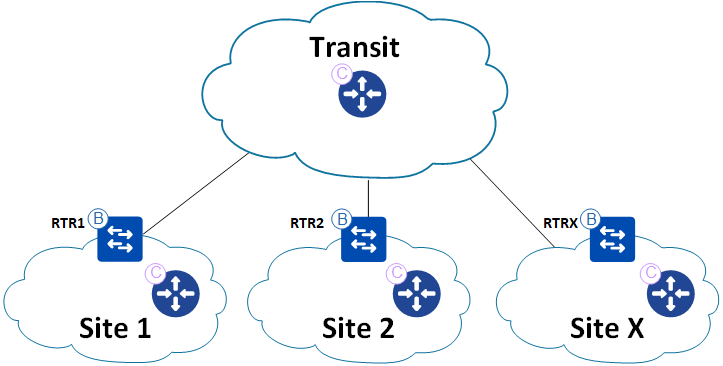
Here, regular fabric sites are stub networks and the inter-connection between them is facilitated using LISP in a hierarchical manner. If EID-SITE-2 wants to communicate with EID-SITE-1, the Edge node will do a LISP lookup to the control plane node of Site 2. A LISP lookup miss will cause the Edge node to encapsulate the packet and send it to the border of Site 2. Here a similar lookup is made but for the transit control plane node. Since all borders register summary prefixes of the EID space for their respective sites, the transit CP node knows the authoritative border who registered the prefix and can send a Map-Reply. Now the border of site 2 can encapsulate the packet in VXLAN and send it to the border of site 1. Here another LISP lookup is made and eventually the packet will make it to the Edge node of Site 1 where EID-SITE-1 is connected. The same hierarchical LISP lookup process will happen in the reverse direction when EID-SITE-1 replies to EID-SITE-2.
The relevant configuration of the border is this:
! B1-SITE-2:
router lisp
 !
 prefix-list Global/Fabric_Site_2_Multisite_LAB_list1
  10.0.2.0/24
  exit-prefix-list
 !
 instance-id 4099
  service ipv4
   eid-table vrf Users
   map-cache 0.0.0.0/0 map-request
   route-import map-cache bgp 65002 route-map permit-all-eids
   route-import database bgp 65002 route-map site-local-eids locator-set rloc_3adb4a21-230f-4f81-af6b-db2e0bc90ea6 proxy
   route-import prefix-list Global/Fabric_Site_2_Multisite_LAB_list1 bgp 65002 route-map site-local-eids
   itr map-resolver 100.127.0.100
   itr map-resolver 100.127.2.100 prefix-list Global/Fabric_Site_2_Multisite_LAB_list1
   etr map-server 100.127.0.100 key 7 <secret>
   etr map-server 100.127.0.100 proxy-reply
   use-petr 100.127.1.1
So, for the prefixes local to this site, the local CP node is consulted. All other lookups go to the transit CP node. Here the imported prefixes (which are summarized) are also registered. If a LISP lookup miss happens, the traffic is encapsulated in VXLAN and sent to the border of Site 1 - 100.127.1.1. This configuration is caused by this checkmark of B1-SITE-1 in DNAC:

This is how the LISP cache looks after the border of site 2 did a lookup of EID-SITE-1:
B1-SITE-2#sh lisp eid-table vrf Users ipv4 map-cache 10.0.1.11
LISP IPv4 Mapping Cache for EID-table vrf Users (IID 4099), 8 entries

10.0.1.0/24, uptime: 00:26:23, expires: 23:33:36, via map-reply, complete
  Sources: map-reply
  State: complete, last modified: 00:26:23, map-source: 100.127.1.2
  Exempt, Packets out: 199(17212 bytes) (~ 00:01:28 ago)
  Configured as EID address space
  Locator      Uptime    State      Pri/Wgt     Encap-IID
  100.127.1.1  00:26:23  up          10/10        -
    Last up-down state change:         00:26:23, state change count: 1
    Last route reachability change:    00:26:23, state change count: 1
    Last priority / weight change:     never/never
    RLOC-probing loc-status algorithm:
      Last RLOC-probe sent:            00:26:23 (rtt 1ms)
  100.127.1.2  00:26:23  up          10/10        -
    Last up-down state change:         00:26:23, state change count: 1
    Last route reachability change:    00:26:23, state change count: 1
    Last priority / weight change:     never/never
    RLOC-probing loc-status algorithm:
      Last RLOC-probe sent:            00:26:23 (rtt 2ms)
B1-SITE-2#
A debug of the LISP lookup on B1-SITE-1 also confirms the LISP hierarchy of SDA transit:
May 25 09:16:30.278: [XTR] LISP: Processing data signal for EID prefix IID 4099 10.0.1.11/32
May 25 09:16:30.278: [XTR] LISP-0: Remote EID IID 4099 prefix 10.0.1.11/32, Change state to incomplete (sources: <signal>, state: unknown, rlocs: 0).
May 25 09:16:30.278: [XTR] LISP-0: Remote EID IID 4099 prefix 10.0.1.11/32, [incomplete] Scheduling map requests delay 00:00:00 min_elapsed 00:00:01 (sources: <signal>, state: incomplete, rlocs: 0).
May 25 09:16:30.278: [XTR] LISP-0: Remote EID IID 4099 prefix 10.0.1.11/32, Starting idle timer (delay 00:02:30) (sources: <signal>, state: incomplete, rlocs: 0).
May 25 09:16:30.407:       LISP-0: IID 4099 Request processing of remote EID prefix map requests to IPv4.
May 25 09:16:30.407: [XTR] LISP: Send map request type remote EID prefix
May 25 09:16:30.407: [XTR] LISP: Send map request for EID prefix IID 4099 10.0.1.11/32
May 25 09:16:30.407: [XTR] LISP-0: Remote EID IID 4099 prefix 10.0.1.11/32, Send map request (1) (sources: <signal>, state: incomplete, rlocs: 0).
May 25 09:16:30.407:       LISP-0: EID-AF IPv4, Sending map-request from 10.0.1.11 to 10.0.1.11 for EID 10.0.1.11/32, ITR-RLOCs 1, nonce 0x27EEB4B2-0x76D0EA93 (encap src 100.127.2.1, dst 100.127.0.100), FromPITR.
May 25 09:16:30.410: [XTR] LISP: Processing received Map-Reply(2) message on Vlan201 from 100.127.0.100:4342 to 100.127.2.1:4342
May 25 09:16:30.410: [XTR] LISP: Received map reply nonce 0x27EEB4B2-0x76D0EA93, records 1
May 25 09:16:30.410: [XTR] LISP: Processing Map-Reply mapping record for IID 4099 SVC_IP_IAF_IPv4 10.0.1.0/24 LCAF 2, ttl 1440, action none, not authoritative, 2 locators
        100.127.1.1 pri/wei=10/10 lpR
        100.127.1.2 pri/wei=10/10 lpR
May 25 09:16:30.410: [XTR] LISP-0: Map Request IID 4099 prefix 10.0.1.11/32 remote EID prefix[LL], Received reply with rtt 2ms.
A LISP lookup for 10.0.1.11 (EID-SITE-1) is sent to 100.127.0.100, the CP transit node. The Map-Reply lists the aggregated prefix 10.0.1.0/24 with 2 locators (borders). Each have equal priority and weight meaning both will be used equally. This is similar to how ECMP works for regular IP forwarding.
Direct Internet Access
At Site 2 a need for DIA exists. Let’s see what the edge and border nodes of Site 2 will do with a packet for 8.8.8.8:
E1-SITE-2#sh ip cef vrf Users 8.8.8.8 detail
0.0.0.0/0, epoch 0, flags [cover dependents, subtree context, check lisp eligibility, default route]
  SC owned,sourced: LISP remote EID - locator status bits 0x00000000
  LISP remote EID: 32 packets 12446 bytes fwd action signal-fwd, cfg as EID space
  LISP source path list
    nexthop 100.127.2.1 LISP0.4099
  Covered dependent prefixes: 2
    notify cover updated: 2
  2 IPL sources [no flags]
  nexthop 100.127.2.1 LISP0.4099
E1-SITE-2#
First the edge node. Here the expected behavior is shown. LISP is used to forward traffic to this destination. Specifically the border of Site 2 will receive the traffic. What does the border do?
B1-SITE-2#sh ip cef vrf Users 8.8.8.8 detail
0.0.0.0/0, epoch 0, flags [cover dependents, subtree context, rib only nolabel, check lisp eligibility, default route]
  SC owned,sourced: LISP remote EID - locator status bits 0x00000000
  LISP remote EID: 13 packets 6482 bytes fwd action signal-fwd, cfg as EID space
  LISP source path list
    nexthop 100.127.1.1 LISP0.4099
  Covered dependent prefixes: 5
    notify cover updated: 5
  2 IPL sources [no flags]
  nexthop 100.127.1.1 LISP0.4099
B1-SITE-2#
Again we see LISP being used. This time the traffic will be forwarded to the border of Site 1 (because of the “internet” checkmark configured in DNAC as we saw with our multi-site LISP discoveries in the last section).
So we must have some routing towards the internet for establishing the DIA for the Users VN. To keep things simple, let’s configure a static default route towards the firewall, F1-SITE-2, on the border:
B1-SITE-2(config)#ip route vrf Users 0.0.0.0 0.0.0.0 100.126.201.2
B1-SITE-2(config)#end
B1-SITE-2#ping vrf Users 100.126.201.2
Type escape sequence to abort.
Sending 5, 100-byte ICMP Echos to 100.126.201.2, timeout is 2 seconds:
!!!!!
Success rate is 100 percent (5/5), round-trip min/avg/max = 1/1/2 ms
B1-SITE-2#
Just to ensure that we’re in fact forwarding the traffic to the firewall a debug of ICMP confirms:
F1-SITE-2#
May 25 10:09:51.500: ICMP: echo reply sent, src 100.126.201.2, dst 100.126.201.1, topology BASE, dscp 0 topoid 0
May 25 10:09:51.501: ICMP: echo reply sent, src 100.126.201.2, dst 100.126.201.1, topology BASE, dscp 0 topoid 0
May 25 10:09:51.503: ICMP: echo reply sent, src 100.126.201.2, dst 100.126.201.1, topology BASE, dscp 0 topoid 0
May 25 10:09:51.505: ICMP: echo reply sent, src 100.126.201.2, dst 100.126.201.1, topology BASE, dscp 0 topoid 0
May 25 10:09:51.506: ICMP: echo reply sent, src 100.126.201.2, dst 100.126.201.1, topology BASE, dscp 0 topoid 0
F1-SITE-2#
To simulate the internet, a loopback interface has been created on the firewall:
! F1-SITE-2
interface Loopback8
 ip address 8.8.8.8 255.255.255.255
Let’s see if it works by pinging 8.8.8.8 from EID-SITE-2 (simulated by a router):
SDA-EP#ping vrf Site2_Users 8.8.8.8 so vlan12

Type escape sequence to abort.
Sending 5, 100-byte ICMP Echos to 8.8.8.8, timeout is 2 seconds:
Packet sent with a source address of 10.0.2.11
!!!!!
Success rate is 100 percent (5/5), round-trip min/avg/max = 1/3/4 ms
SDA-EP#
Success! Let’s verify that the packets hit our firewall again:
F1-SITE-2#
Hmm… Nothing! I happen to have configured a loopback on B1-SITE-1 too:
! B1-SITE-1:
interface Loopback8
 vrf forwarding Users
 ip address 8.8.8.8 255.255.255.255
Debug of ICMP is also running here, and this is shown:
B1-SITE-1#
May 25 10:12:45.704: ICMP: echo reply sent, src 8.8.8.8, dst 10.0.2.11, topology BASE, dscp 0 topoid 2
May 25 10:12:45.704: ICMP: echo reply sent, src 8.8.8.8, dst 10.0.2.11, topology BASE, dscp 0 topoid 2
May 25 10:12:45.704: ICMP: echo reply sent, src 8.8.8.8, dst 10.0.2.11, topology BASE, dscp 0 topoid 2
May 25 10:12:45.705: ICMP: echo reply sent, src 8.8.8.8, dst 10.0.2.11, topology BASE, dscp 0 topoid 2
B1-SITE-1#
So, why is the traffic forwarded to B1-SITE-1? LISP is still used and takes precedence over regular IP routing when it comes to a default route:
B1-SITE-2#sh ip cef vrf Users 8.8.8.8 detail
8.0.0.0/7, epoch 0, flags [subtree context, check lisp eligibility]
  SC owned,sourced: LISP remote EID - locator status bits 0x00000000
  LISP remote EID: 2 packets 1152 bytes fwd action encap, cfg as EID space
  LISP source path list
    nexthop 100.127.1.1 LISP0.4099
  2 IPL sources [no flags]
  nexthop 100.127.1.1 LISP0.4099
B1-SITE-2#
So, to actually work around this behavior, we can configure specific non-default routes:
B1-SITE-2(config)#ip route vrf Users 8.8.8.8 255.255.255.255 100.126.201.2
B1-SITE-2(config)#end
B1-SITE-2#sh ip cef vrf Users 8.8.8.8 detail
8.8.8.8/32, epoch 0, flags [subtree context]
  SC inherited: LISP remote EID - locator status bits 0x00000000
  recursive via 100.126.201.2
    attached to Vlan3212
B1-SITE-2#
And ping again:
SDA-EP#ping vrf Site2_Users 8.8.8.8 so vlan12

Type escape sequence to abort.
Sending 5, 100-byte ICMP Echos to 8.8.8.8, timeout is 2 seconds:
Packet sent with a source address of 10.0.2.11
!!!!!
Success rate is 100 percent (5/5), round-trip min/avg/max = 1/2/4 ms
SDA-EP#
Let’s check the firewall:
F1-SITE-2#
May 25 10:21:44.909: ICMP: echo reply sent, src 8.8.8.8, dst 10.0.2.11, topology BASE, dscp 0 topoid 0
May 25 10:21:44.913: ICMP: echo reply sent, src 8.8.8.8, dst 10.0.2.11, topology BASE, dscp 0 topoid 0
May 25 10:21:44.918: ICMP: echo reply sent, src 8.8.8.8, dst 10.0.2.11, topology BASE, dscp 0 topoid 0
May 25 10:21:44.922: ICMP: echo reply sent, src 8.8.8.8, dst 10.0.2.11, topology BASE, dscp 0 topoid 0
May 25 10:21:44.925: ICMP: echo reply sent, src 8.8.8.8, dst 10.0.2.11, topology BASE, dscp 0 topoid 0
F1-SITE-2#
Now we certainly have a successful DIA configured!
Static Internet Routing Table
Since the workaround for fixing the order of operation is to use non-default routing with SDA DIA, you might think that this isn’t scalable. But if we use a bit of subnetting and create some aggregated routes, it isn’t that bad:
ip route vrf Users 1.0.0.0 255.0.0.0 100.126.201.2
ip route vrf Users 2.0.0.0 254.0.0.0 100.126.201.2
ip route vrf Users 4.0.0.0 252.0.0.0 100.126.201.2
ip route vrf Users 8.0.0.0 254.0.0.0 100.126.201.2
ip route vrf Users 11.0.0.0 255.0.0.0 100.126.201.2
ip route vrf Users 12.0.0.0 252.0.0.0 100.126.201.2
ip route vrf Users 16.0.0.0 240.0.0.0 100.126.201.2
ip route vrf Users 32.0.0.0 224.0.0.0 100.126.201.2
ip route vrf Users 64.0.0.0 224.0.0.0 100.126.201.2
ip route vrf Users 96.0.0.0 252.0.0.0 100.126.201.2
ip route vrf Users 100.0.0.0 255.192.0.0 100.126.201.2
ip route vrf Users 100.128.0.0 255.128.0.0 100.126.201.2
ip route vrf Users 101.0.0.0 255.0.0.0 100.126.201.2
ip route vrf Users 102.0.0.0 254.0.0.0 100.126.201.2
ip route vrf Users 104.0.0.0 248.0.0.0 100.126.201.2
ip route vrf Users 112.0.0.0 248.0.0.0 100.126.201.2
ip route vrf Users 120.0.0.0 252.0.0.0 100.126.201.2
ip route vrf Users 124.0.0.0 254.0.0.0 100.126.201.2
ip route vrf Users 126.0.0.0 255.0.0.0 100.126.201.2
ip route vrf Users 128.0.0.0 224.0.0.0 100.126.201.2
ip route vrf Users 160.0.0.0 248.0.0.0 100.126.201.2
ip route vrf Users 168.0.0.0 255.0.0.0 100.126.201.2
ip route vrf Users 170.0.0.0 254.0.0.0 100.126.201.2
ip route vrf Users 172.0.0.0 255.240.0.0 100.126.201.2
ip route vrf Users 172.32.0.0 255.224.0.0 100.126.201.2
ip route vrf Users 172.64.0.0 255.192.0.0 100.126.201.2
ip route vrf Users 172.128.0.0 255.128.0.0 100.126.201.2
ip route vrf Users 173.0.0.0 255.0.0.0 100.126.201.2
ip route vrf Users 174.0.0.0 254.0.0.0 100.126.201.2
ip route vrf Users 176.0.0.0 240.0.0.0 100.126.201.2
ip route vrf Users 192.0.1.0 255.255.255.0 100.126.201.2
ip route vrf Users 192.0.3.0 255.255.255.0 100.126.201.2
ip route vrf Users 192.0.4.0 255.255.252.0 100.126.201.2
ip route vrf Users 192.0.8.0 255.255.248.0 100.126.201.2
ip route vrf Users 192.0.16.0 255.255.240.0 100.126.201.2
ip route vrf Users 192.0.32.0 255.255.224.0 100.126.201.2
ip route vrf Users 192.0.64.0 255.255.192.0 100.126.201.2
ip route vrf Users 192.0.128.0 255.255.128.0 100.126.201.2
ip route vrf Users 192.1.0.0 255.255.0.0 100.126.201.2
ip route vrf Users 192.2.0.0 255.254.0.0 100.126.201.2
ip route vrf Users 192.4.0.0 255.252.0.0 100.126.201.2
ip route vrf Users 192.8.0.0 255.248.0.0 100.126.201.2
ip route vrf Users 192.16.0.0 255.240.0.0 100.126.201.2
ip route vrf Users 192.32.0.0 255.224.0.0 100.126.201.2
ip route vrf Users 192.64.0.0 255.192.0.0 100.126.201.2
ip route vrf Users 192.128.0.0 255.224.0.0 100.126.201.2
ip route vrf Users 192.160.0.0 255.248.0.0 100.126.201.2
ip route vrf Users 192.169.0.0 255.255.0.0 100.126.201.2
ip route vrf Users 192.170.0.0 255.254.0.0 100.126.201.2
ip route vrf Users 192.172.0.0 255.252.0.0 100.126.201.2
ip route vrf Users 192.176.0.0 255.240.0.0 100.126.201.2
ip route vrf Users 192.192.0.0 255.192.0.0 100.126.201.2
ip route vrf Users 193.0.0.0 255.0.0.0 100.126.201.2
ip route vrf Users 194.0.0.0 254.0.0.0 100.126.201.2
ip route vrf Users 196.0.0.0 254.0.0.0 100.126.201.2
ip route vrf Users 198.0.0.0 255.240.0.0 100.126.201.2
ip route vrf Users 198.16.0.0 255.240.0.0 100.126.201.2
ip route vrf Users 198.17.0.0 255.255.0.0 100.126.201.2
ip route vrf Users 198.20.0.0 255.252.0.0 100.126.201.2
ip route vrf Users 198.24.0.0 255.248.0.0 100.126.201.2
ip route vrf Users 198.32.0.0 255.240.0.0 100.126.201.2
ip route vrf Users 198.48.0.0 255.254.0.0 100.126.201.2
ip route vrf Users 198.50.0.0 255.255.0.0 100.126.201.2
ip route vrf Users 198.51.0.0 255.255.192.0 100.126.201.2
ip route vrf Users 198.51.64.0 255.255.224.0 100.126.201.2
ip route vrf Users 198.51.96.0 255.255.252.0 100.126.201.2
ip route vrf Users 198.51.101.0 255.255.255.0 100.126.201.2
ip route vrf Users 198.51.102.0 255.255.254.0 100.126.201.2
ip route vrf Users 198.51.104.0 255.255.248.0 100.126.201.2
ip route vrf Users 198.51.112.0 255.255.240.0 100.126.201.2
ip route vrf Users 198.51.128.0 255.255.128.0 100.126.201.2
ip route vrf Users 198.52.0.0 255.252.0.0 100.126.201.2
ip route vrf Users 198.56.0.0 255.248.0.0 100.126.201.2
ip route vrf Users 198.64.0.0 255.192.0.0 100.126.201.2
ip route vrf Users 198.128.0.0 255.128.0.0 100.126.201.2
ip route vrf Users 199.0.0.0 255.0.0.0 100.126.201.2
ip route vrf Users 200.0.0.0 254.0.0.0 100.126.201.2
ip route vrf Users 202.0.0.0 255.0.0.0 100.126.201.2
ip route vrf Users 203.0.0.0 255.255.192.0 100.126.201.2
ip route vrf Users 203.0.64.0 255.255.224.0 100.126.201.2
ip route vrf Users 203.0.96.0 255.255.240.0 100.126.201.2
ip route vrf Users 203.0.112.0 255.255.255.0 100.126.201.2
ip route vrf Users 203.0.114.0 255.255.254.0 100.126.201.2
ip route vrf Users 203.0.116.0 255.255.252.0 100.126.201.2
ip route vrf Users 203.0.120.0 255.255.248.0 100.126.201.2
ip route vrf Users 203.0.128.0 255.255.128.0 100.126.201.2
ip route vrf Users 204.0.0.0 252.0.0.0 100.126.201.2
ip route vrf Users 208.0.0.0 240.0.0.0 100.126.201.2
Here I’ve excluded these bogons:
0.0.0.0 255.0.0.0
10.0.0.0 255.0.0.0
100.64.0.0 255.192.0.0
127.0.0.0 255.0.0.0
169.254.0.0 255.255.0.0
172.16.0.0 255.240.0.0
192.0.0.0 255.255.255.0
192.0.2.0 255.255.255.0
192.168.0.0 255.255.0.0
198.18.0.0 255.254.0.0
198.51.100.0 255.255.255.0
203.0.113.0 255.255.255.0
224.0.0.0 240.0.0.0
240.0.0.0 240.0.0.0
The list can be found at Team Cymru
Other references are:
Now, the requirement for the Users VN was that users be able to reach the internet via local breakout and reach central services and other users in the other sites. Let’s see if a user in Site 2 is still able to reach a user in Site 1:
SDA-EP#ping vrf Site2_Users 10.0.1.11 so vlan12

Type escape sequence to abort.
Sending 5, 100-byte ICMP Echos to 10.0.1.11, timeout is 2 seconds:
Packet sent with a source address of 10.0.2.11
!!!!!
Success rate is 100 percent (5/5), round-trip min/avg/max = 1/3/4 ms
SDA-EP#
It does indeed work.
Conclusion
In this post we covered the SDA use case for DIA with SDA transit. The various border configuration options and the configuration of the chosen external border for this setup was displayed and explained.
A foundational walkthrough of the LISP control plane in a multi-site solution with SDA transit was shown along with relevant configurations and debugs. Specifically the “This site provides internet access to other sites through SDA Transit” was explained.
The DIA section builds upon the multi-site LISP walkthrough explaining why you cannot just rely on a default route with LISP in the control plane. More specific non-default routes must be used.
Lastly a reference to a complete static internet routing table was listed along with references to bogons and RFCs for special purpose IP addresses.
I hope you enjoyed reading this post. Please do not hesitate contacting me for any feedback you may have. Thanks.