Spanning-Tree Protocol
I’ve always found STP a bit confusing. Partly because STP was designed in a time where L2 was a good way to do things. Nowadays building a network with heavy focus on L2 domains is obsolete IMHO. We do whatever we can to avoid having STP block links by using port-channels and routed links.
I will concentrate only on the flavors of STP that newer Catalyst switches support.
- Legacy STP
        <li>
          <a href="#Port_Roles">Port Roles</a>
        </li>
        <li>
          <a href="#Port_States">Port States</a>
        </li>
        <li>
          <a href="#Topology_Change">Topology Change</a><ul>
            <li>
              <a href="#Notify_The_Root">Notify The Root</a>
            </li>
            <li>
              <a href="#Notify_The_Network">Notify The Network</a>
            </li>
          </ul>
        </li>

        <li>
          <a href="#Traffic_Engineering">Traffic Engineering</a>
        </li>
        <li>
          <a href="#STP_On_The_Wire">STP On The Wire</a>
        </li>
        <li>
          <a href="#Optional_Features">Optional Features</a><ul>
            <li>
              <a href="#PortFast">PortFast</a>
            </li>
            <li>
              <a href="#BPDU_Guard">BPDU Guard</a>
            </li>
            <li>
              <a href="#BPDU_Filter">BPDU Filter</a>
            </li>
            <li>
              <a href="#Loopguard">Loopguard</a>
            </li>
          </ul>
        </li>
      </ul>
    </li>
  </ul>
</li>

<li>
  <a href="#RSTPMST">RSTP/MST</a>
</li>
Legacy STP
Aka. PVST+. The default mode running on most Catalyst switches today. It is a timer driven flavor of STP and therefore slow to converge.
Timers
STP timers are set by the root bridge via the BPDU. If you configure other timers on a non-root switch, they will not have any effect until this switch become root bridge.
[table id=3 /]
BPDU Timers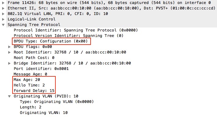
Root Bridge Election
The root bridge is the reference point for all switches. It is the first step in converging. To elect a root bridge all switches start by sending BPDUs on a per-VLAN basis. Each received BPDU is compared to the locally generated BPDU. The one with the lowest Root Bridge ID (BID) wins and this BPDU is relayed to other switches after updating a few fields of the header:
- Root path cost (RPC)
- Upstream BID
- Upstream PID
- MessageAge
MessageAge is set to 0 by the root and is incremented by 1 at every switch downstream. It is used to determine how long the switch will keep the received BPDU – a period of MaxAge-MessageAge seconds.
Bridge ID
The Bridge ID is made up of two pieces:
Priority - 0-61440 (default: 32768)
MAC address
The Priority is given in increments of 4096 because of the extended-system ID feature which is required to create a unique BID per VLAN as STP runs a separate process per VLAN with PVST+. The extended-system ID is simply the VLAN ID, meaning that for VLAN 10 the BID will be:
32778 / MAC
Bridge ID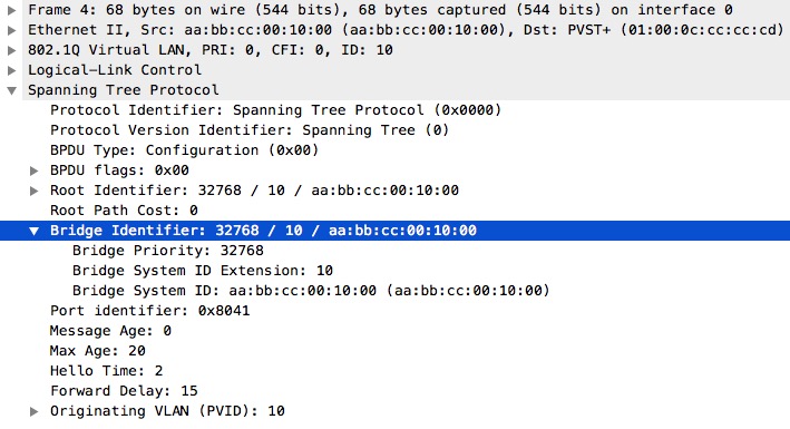
Bridge ID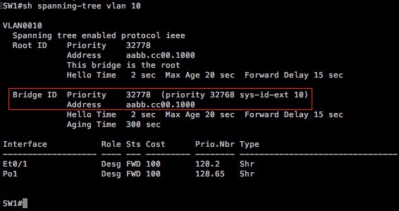
Port Roles
Once the Root Bridge is elected, it is time to figure out the port roles. A crucial step in loop prevention. Making sure only one physical path is forwarding at any given time. A huge drawback of relying on STP for redundant networks IMHO. The election is based on the cost to reach the root.
First determine the root port (RP). This is the port that received the BPDU with the lowest root path cost (RPC) among all ports that received a BPDU.
Next choose the designated (downstream) ports (DP). Again this is the one with the lowest RPC compared in the received BPDU(s) on that port. If the RPC is equal, these tiebreakers are followed: (lower value is better)
- Upstream BID
- Upstream PID (Port ID)
- More than one link to the same upstream switch
- Local Port ID
- A hub is involved
Any ports that were not elected as RP or DP are considered non-designated and are always in the blocking (BLK) state avoiding loops.
Port States
PVST+ has five port states:
- Blocking (BLK)
- non-DP
- Listening (LIS)
- This is where elections are held (choosing root bridge, RP, DP and non-DP)
- Learning (LRN)
- Populate the CAM table and drop the received frame afterwards (no forwarding yet)
- Forwarding (FWD)
- Disabled
- Not participating in STP
Notice only Blocking, Forwarding, and Disabled are steady states – no convergence.
Topology Change
With legacy STP a topology change occurs on these events:
- A port goes down (or into blocking state)
- A port goes into forwarding state
- A new RP is elected
- A new root bridge is elected
Notify The Root
If any of the above events happen on a switch, it will send TCN out its root port every hello time until the upstream bridge sends a TCA back. The upstream bridge will forward the TCN out its root port and wait for a TCA until it finally reaches the root bridge.
The content of the TCN is at a bare minimum, just to inform the root of a TC.
TCN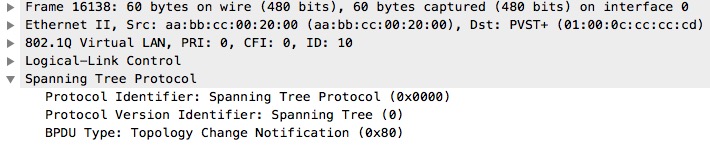
Notify The Network
When the root bridge receives a TCN, it has to notify the rest of the switches about the TC. The reason for this is to make them lower their CAM entries age time to the FWD DLY timer so blackholes can be avoided. Remember the default CAM aging timer is 5 minutes. Imagine having a path to a destination through a link that suddenly fails. CAM table entries are created based on dataplane. Traffic received on a port creates an entry in the CAM table using the source MAC address of a frame received. The switches do not know the destination can’t be reached via the link it used to, meaning all traffic to devices out the failed link will be blackholed as long as CAM tables are not corrected. Timing out the stale information of the CAM tables will make switches flood traffic (unknown unicast/broadcast) to re-learn the MAC addresses through the new path. This is why you shouldn’t use STP when building redundant network. Relying on convergence as a function of dataplane is a huge mistake IMHO.
Upon receiving a TCN, the root bridge starts sending out configuration BPDUs with the TC flag set.
TC flag set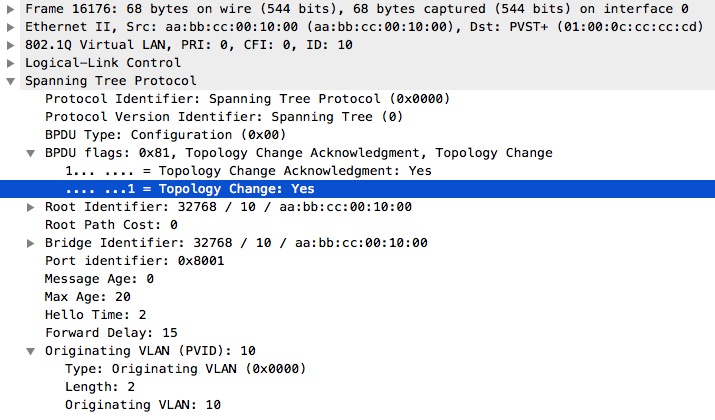
The root bridge sends TC for a period of FWD DLY+MaxAge. The TC is received on all ports downstream – including BLK ports.
Traffic Engineering
We have a few knobs available when we want to steer traffic a certain way. This is done by affecting which ports will be in the BLK state. To determine this we must know the criteria for choosing the BLK ports: (remember lower is better)
- RPC
- Upstream BID
- Upstream PID
- Local PID
So the easiest and probably the most used way of influencing the path to the root is using cost on the upstream interface.
[table id=1 /]
SW1 below is the root bridge because it has the lowest BID among all switches. Next we can determine the RP and DPs of downstream switches, SW2 and SW3.
RPC Tie Breaker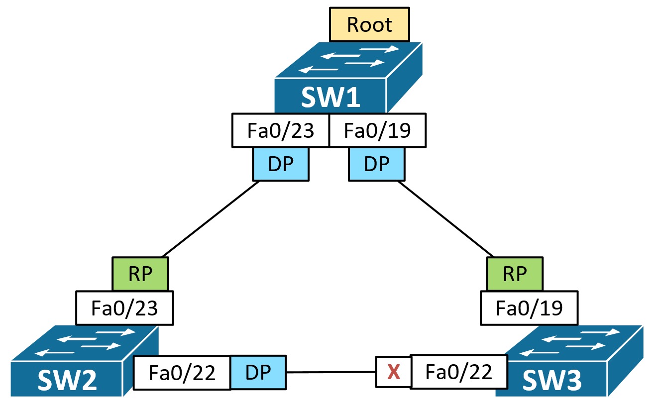
Suppose we want the link between SW2 and SW3 to be blocked on SW2 instead of SW3, we could change the cost on SW2 fa0/23 to a high value. Or if restricted, we could change SW3 bridge priority to a lower value. Be careful though not to change which switch is the root bridge! You’ll do this by setting the priority on SW3 to a value lower than 4096 (0 would be the only option).
When influencing path selection with STP using any “ID” of the tiebreakers listed above, you only have the ability to change the priority value of the ID. An ID in STP is made up of two pieces – a priority and a fixed value:
[table id=2 /]
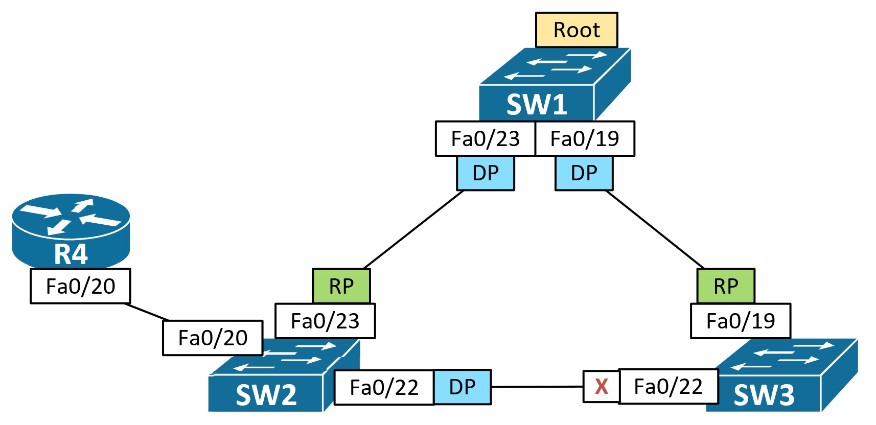
If we add link redundancy between SW2 and SW3 and unplug the cable between SW1 and SW3, we get this state of STP:
Upstream PID Tie Breaker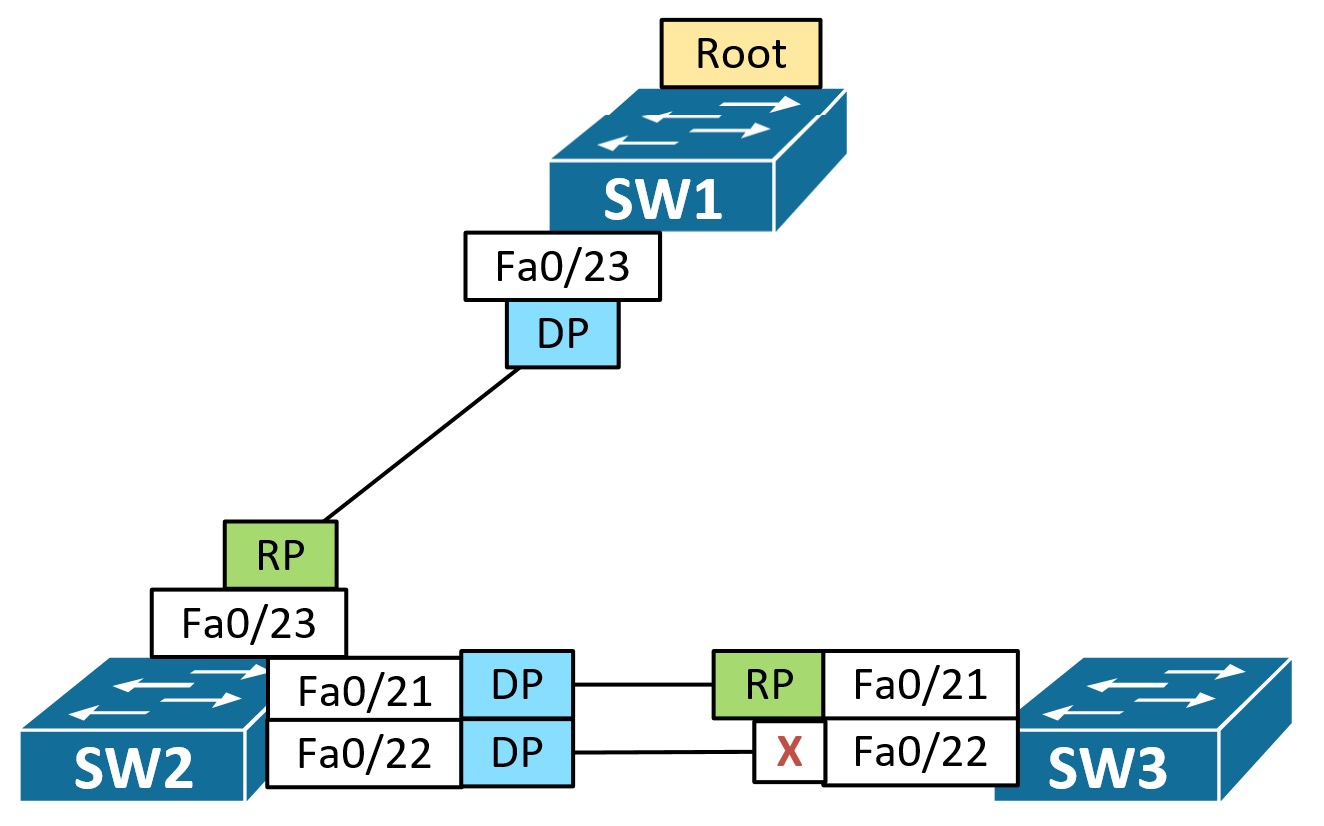
Here SW3 e0/2 is BLK because RPC is the same and Upstream BID is better from SW2. We then must look at the Upstream PID. And lower is better, meaning e0/1 is better then e0/2 (numerically higher PID/worse), so e0/2 is BLK.
Local PID Tie Breaker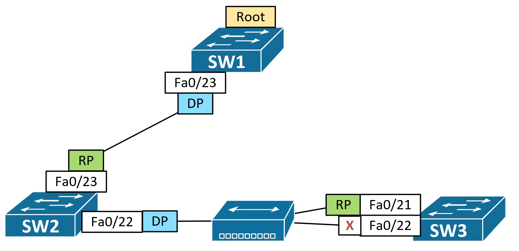
With a hub in the picture, both RPC, Upstream BID, and Upstream PID are the same seen on SW3 (received from SW2). Final tie-breaker is Local PID, so e0/2 ends up being BLK on SW3.
Adding the link between SW1 and SW3 back in the last two scenarios, would make e0/0 on SW3 RP and e0/1 BLK.
STP On The Wire
A switch sends out a configuration BPDU for every VLAN it has an STP instance running. The frame has the 802.1Q tag of the VLAN and in the BPDU part a PVID TLV (Port VLAN ID TLV). For the native VLAN the frame should be untagged, but the BPDU part should still contain the PVID TLV. This PVID is used to detect native VLAN mismatches.
Inconsistent Ports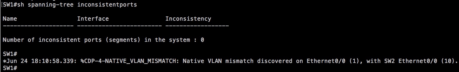
VLAN 1 dot1q tag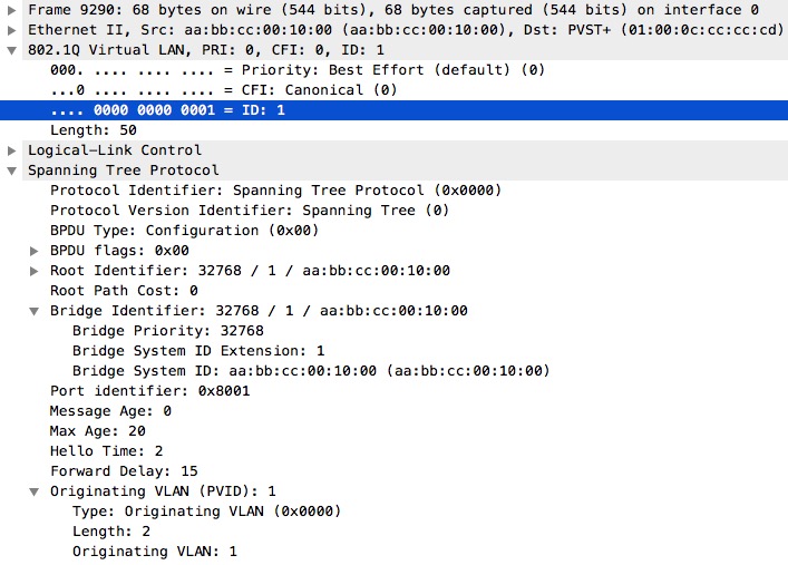
The frame is tagged with VLAN 1 even though this is the native VLAN for this switch! Hence no inconsistent ports are detected. This is possibly because I used IOL L2 images. When I have the time, I will try it out on real switches.
Also notice the destination multicast MAC address 0100.0ccc.cccd of the PVST+ frame. This is the destination for BPDU frames sent out trunk ports (tagged as we saw above). Non-Cisco CST switches will not interpret these frames, but rather transparently relay them through the CST domain and out to possibly another PVST+ domain. Now PVST+ domains can process the frames and participate in the other PVST+ domains STP.
Mixed Environment – PVST+ and CST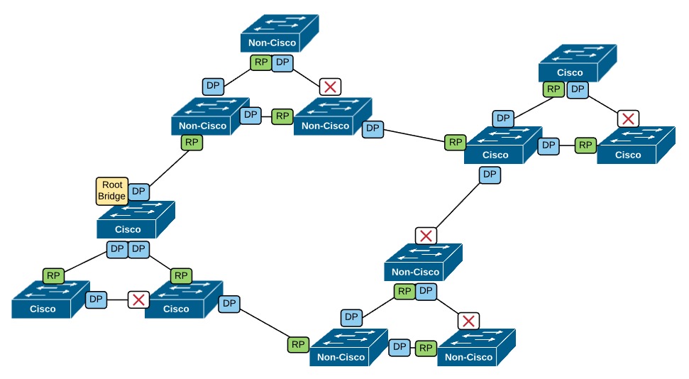
Here we see how the non-Cisco switches are transparent to the PVST+ switches, just functioning as loop free transit (you can replace the islands of Non-Cisco switches with a cable between the Cisco switches).
For interoperability with non-Cisco switches that run CST, Cisco switches sends BPDU frames out all ports (trunk and access). The properties of this special frame are these:
- LLC encapsulation
- Both DSAP and SSAP set to a value of 0x42 for BPDU
- Destination MAC is 0180.c200.0000
- Untagged
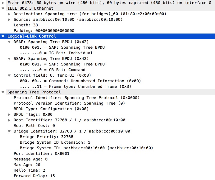
So if you have two VLANs, VLAN 1 and VLAN 10, and a trunk configured, the switch will send out three BPDUs:

A PVST+ BPDU for each VLAN (tagged), and the Spanning-tree-(for-bridges)_00 BPDU.
Optional Features
PortFast
PortFast is the feature of STP you can’t live without. It works by making an access port transition to FWD immediately without going through the FWD DLY states Listening and Learning. If you configure PortFast on a trunk port, the feature will remain disabled. What if you have a VMware host and a trunk to this server? Depending on the code you’re running, you can enable PortFast on trunk ports by specifying the keyword trunk or edge on the command.
Another benefit of using PortFast is that no TCN is generated upon link up/down with an PortFast enabled port! This is good because no TC will be sent out by the root, and therefore no CAM table entries will be flushed.
If we configure SW2 fa/20 for portfast trunk/portfast edge trunk, we not only bypass the LIS and LRN states of STP, but also prevent STP convergence when the port goes up/down.
PortFast Trunk Configuration[
]3 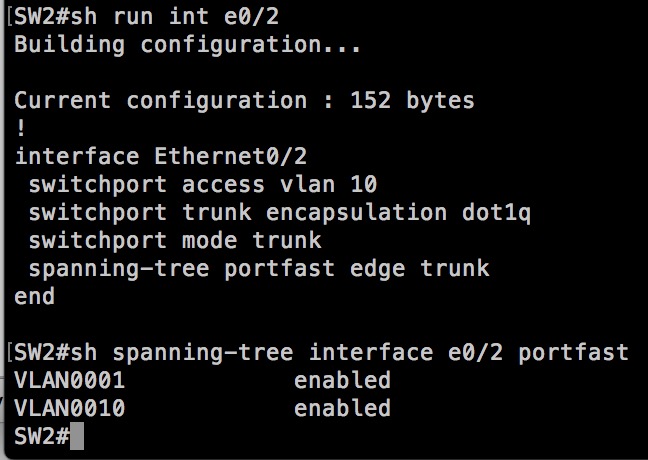 [
[
]3
One might argue, that PortFast is a dangerous  feature, but with both the PortFast single VLAN (access port) and trunk port feature, when the switch receives a BPDU, it will revert to regular STP rules and transition the port through the LIS and LRN states before FWD or BLK.
You can enable PortFast for all ports in the access mode via one global command:
SW1(config)#spanning-tree portfast default
or
SW1(config)#spanning-tree portfast edge default
Let’s have a look at the effect.
PortFast Default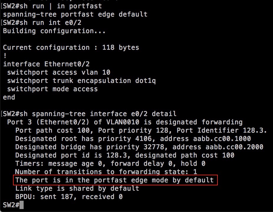
BPDU Guard
Err-disables a port upon receiving a BPDU. Useful on access ports where you do not want users to connect switches!
BPDU Filter
Usually people are very careful when enabling BPDU Filter – if they ever do it! And care should be taken when thinking about enabling this feature. First of all you’d use BPDU Filter to separate STP domains, or simply prevent sending/processing BPDUs on an interface connecting to provider equipment. This is when enabled directly on a port. Like BPDU Guard you can enable BPDU Filter globally. The function of the feature however when enabled globally affects only portfast enabled ports. It also changes the way the port acts. Firstly the interface will transmit exactly 11 BPDUs to try to detect if another BPDU capable device should be connected to this port. If nothing is received back, the interface simply stops sending BPDUs. But, should a BPDU be received later, the port will loose its PortFast status, therefore also its BPDU Filter status, and start converging using regular STP rules – LIS and LRN.
PortFast BPDU Filter Default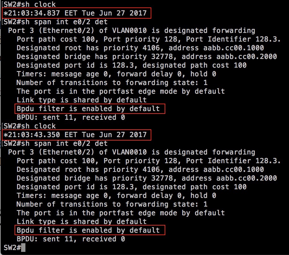
Loopguard
A feature that helps mitigate unidirectional loops. If a BLK port suddenly stops receiving BPDUs because of a unidirectional link (loss of Tx fiber on the peer end) or mis-configured BPDU Filter on the far end port, then loopguard should detect this and put the port into a loop inconsistent state thereby keeping the port blocking and not causing a loop.
RSTP/MST
I will cover those when I have more time.
Â