DMVPN
DMVPN Topology
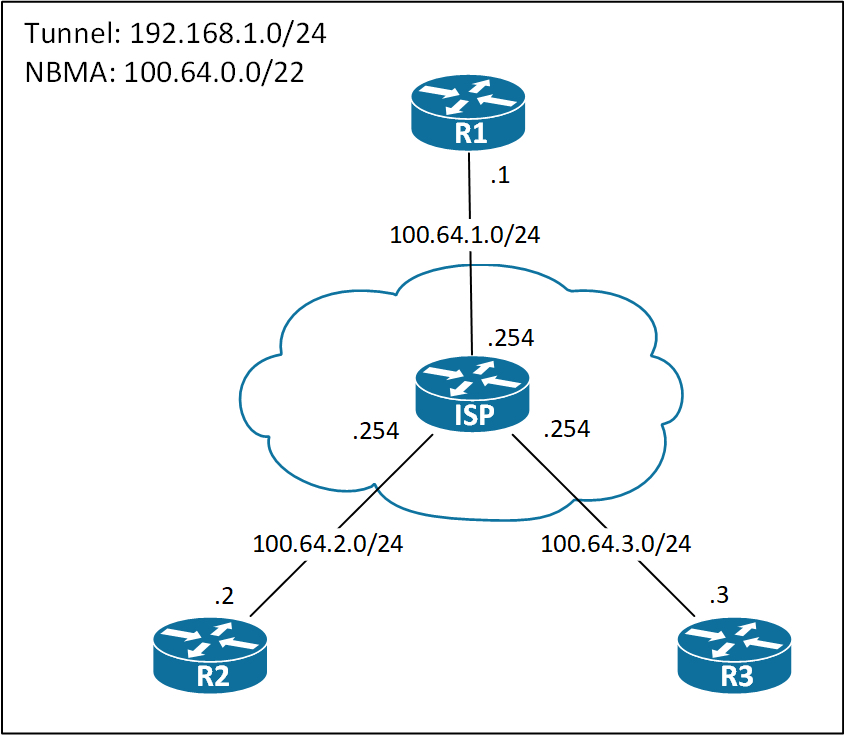
Below you see the DMVPN topology I use for demonstrating various configs in the page.
Phase 1
Not many people use Phase 1, because of its obvious drawback: Every packet between spokes must traverse the Hub. So unless you have a really good reason to do it, use Phase 3 instead.
For completeness of this page, I’ll provide the configurations and talk briefly about them.
! R1 Hub Configuration:
interface Tunnel0
 ip address 192.168.1.1 255.255.255.0
 ip nhrp network-id 1
 tunnel source Ethernet0/0
 tunnel mode gre multipoint
The Hub is always configured with the tunnel mode gre multipoint command, because it needs to address multiple spoke routers.
The only NHRP configuration on the Hub is the ip nhrp network-id command. This command is what enables NHRP on an interface. Without it, NHRP will not function.
Let’s see the Phase 1 spoke configuration.
! R2 Spoke Configuration
int tun0
 ip address 192.168.1.2 255.255.255.0
 ip nhrp map 192.168.1.1 100.64.1.1
 ip nhrp network-id 1
 ip nhrp nhs 192.168.1.1
 tunnel source Ethernet0/0
 tunnel destination 100.64.1.1
On every DMVPN router, we must enable NHRP with the ip nhrp network-id command. This is a mandatory step. The ID is locally significant and does not have to match between routers.
To register tunnel to NBMA address mappings on the Hub which is the NHS (Next Hop Server), the NHC (Next Hop Client(spoke)) must define the IP address of the NHS. This is done using the ip nhrp nhs command.
Phase 2
In Phase 2 both the hub(s) and spokes have multipoint tunnels, meaning direct spoke to spoke communication is possible.
The configuration if fairly simple. The hub is configured the usual way:
! R1 Hub Configuration
interface Tunnel0
 ip address 192.168.1.1 255.255.255.0
 ip nhrp network-id 1
 tunnel source Ethernet0/0
 tunnel mode gre multipoint
Spokes are configured with R1 as the NHS and because of the multipoint interface they must have a static mapping for it.
! R2 Spoke Configuration
interface Tunnel0
 ip address 192.168.1.2 255.255.255.0
 ip nhrp map 192.168.1.1 100.64.1.1
 ip nhrp network-id 1
 ip nhrp nhs 192.168.1.1
 ip nhrp nhs 192.168.1.1
 tunnel source Ethernet0/0
 tunnel mode gre multipoint
Let’s verify the NHRP registrations on the Hub:
! R1 NHRP Mappings
R1#sh ip nhrp
192.168.1.2/32 via 192.168.1.2
Tunnel0 created 00:00:34, expire 01:59:26
Type: dynamic, Flags: unique registered used nhop
NBMA address: 100.64.2.2
192.168.1.3/32 via 192.168.1.3
Tunnel0 created 00:00:02, expire 01:59:58
Type: dynamic, Flags: unique registered used nhop
NBMA address: 100.64.3.3
R1#
So we have the correct mappings on the NHS, R1. This completes the configuration of Phase 2 DMVPN.
NHRP
Now for the fun part. How does R2 communicate with R3? Well if you’ve been doing DMVPN before, you probably know that R2 must do a NHRP resolution request to R1 in order for find R3’s NBMA address. This is the hole nature of DMVPN. But what happens at R1 when it receives the resolution request and what happens on R3 might new to you. You’d think that R1 will just respond to R2’s request directly to R2 and then R2 will initiate a tunnel to R3. This it not the case, though. Let’s have a look.
! Enable NHRP Debugging on R1, R2, and R3
R1#debug nhrp packet
NHRP activity debugging is on
R1#
Do a ping to 192.168.1.3 on R2 and check the debug outputs.
! On R2, ping R3:
R2#ping 192.168.1.3
Type escape sequence to abort.
Sending 5, 100-byte ICMP Echos to 192.168.1.3, timeout is 2 seconds:
.!!!!
The NHRP debug output on R2:
! R2 NHRP Debug output:
*Oct 20 09:39:15.203: NHRP: Send Resolution Request via Tunnel0 vrf 0, packet size: 72
*Oct 20 09:39:15.203: src: 192.168.1.2, dst: 192.168.1.3
*Oct 20 09:39:15.203: (F) afn: AF_IP(1), type: IP(800), hop: 255, ver: 1
*Oct 20 09:39:15.203: shtl: 4(NSAP), sstl: 0(NSAP)
*Oct 20 09:39:15.203: pktsz: 72 extoff: 52
*Oct 20 09:39:15.203: (M) flags: "router auth src-stable nat ", reqid: 4
*Oct 20 09:39:15.203: src NBMA: 100.64.2.2
*Oct 20 09:39:15.203: src protocol: 192.168.1.2, dst protocol: 192.168.1.3
*Oct 20 09:39:15.203: (C-1) code: no error(0)
*Oct 20 09:39:15.203: prefix: 32, mtu: 17916, hd_time: 7200
*Oct 20 09:39:15.203: addr_len: 0(NSAP), subaddr_len: 0(NSAP), proto_len: 0, pref: 0
Nothing special going on here. We see that R2 generates the NHRP Resolution Request as expected. We do not see the content of the IP header here, so we’re uncertain where R2 sends the Resolution Request. I’ve done a Wireshark capture to enforce the flow of the NHRP messages. Below we see the capture for R2’s Resolution Request.
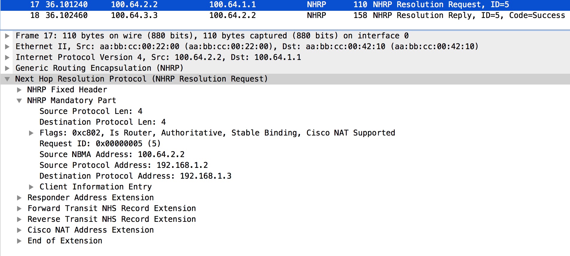
Here we see the IP Src and Dst addresses which clearly is R2 and R3, respectively.
Packet #17 is showing us this. I’ll talk about packet #18 on R2 later.
Looking at the NHRP debug output on R1:
! R1 NHRP Debug output:
*Oct 20 09:39:15.203: NHRP: Receive Resolution Request via Tunnel0 vrf 0, packet size: 72
*Oct 20 09:39:15.203: (F) afn: AF_IP(1), type: IP(800), hop: 255, ver: 1
*Oct 20 09:39:15.203: shtl: 4(NSAP), sstl: 0(NSAP)
*Oct 20 09:39:15.203: pktsz: 72 extoff: 52
*Oct 20 09:39:15.203: (M) flags: "router auth src-stable nat ", reqid: 4
*Oct 20 09:39:15.203: src NBMA: 100.64.2.2
*Oct 20 09:39:15.203: src protocol: 192.168.1.2, dst protocol: 192.168.1.3
*Oct 20 09:39:15.203: (C-1) code: no error(0)
*Oct 20 09:39:15.203: prefix: 32, mtu: 17916, hd_time: 7200
*Oct 20 09:39:15.203: addr_len: 0(NSAP), subaddr_len: 0(NSAP), proto_len: 0, pref: 0
*Oct 20 09:39:15.203: NHRP: Forwarding Resolution Request via Tunnel0 vrf 0, packet size: 92
*Oct 20 09:39:15.203: src: 192.168.1.1, dst: 192.168.1.3
*Oct 20 09:39:15.203: (F) afn: AF_IP(1), type: IP(800), hop: 254, ver: 1
*Oct 20 09:39:15.203: shtl: 4(NSAP), sstl: 0(NSAP)
*Oct 20 09:39:15.203: pktsz: 92 extoff: 52
*Oct 20 09:39:15.203: (M) flags: "router auth src-stable nat ", reqid: 4
*Oct 20 09:39:15.203: src NBMA: 100.64.2.2
*Oct 20 09:39:15.203: src protocol: 192.168.1.2, dst protocol: 192.168.1.3
*Oct 20 09:39:15.203: (C-1) code: no error(0)
*Oct 20 09:39:15.203: prefix: 32, mtu: 17916, hd_time: 7200
*Oct 20 09:39:15.203: addr_len: 0(NSAP), subaddr_len: 0(NSAP), proto_len: 0, pref: 0
This is where something interesting is happening. First we see that R1 receives the NHRP Resolution Request from R2. Secondly we see that R1 is “Forwarding Resolution Request”. This happens to go to R3. We’ll verify this from the Wireshark capture done on R1:
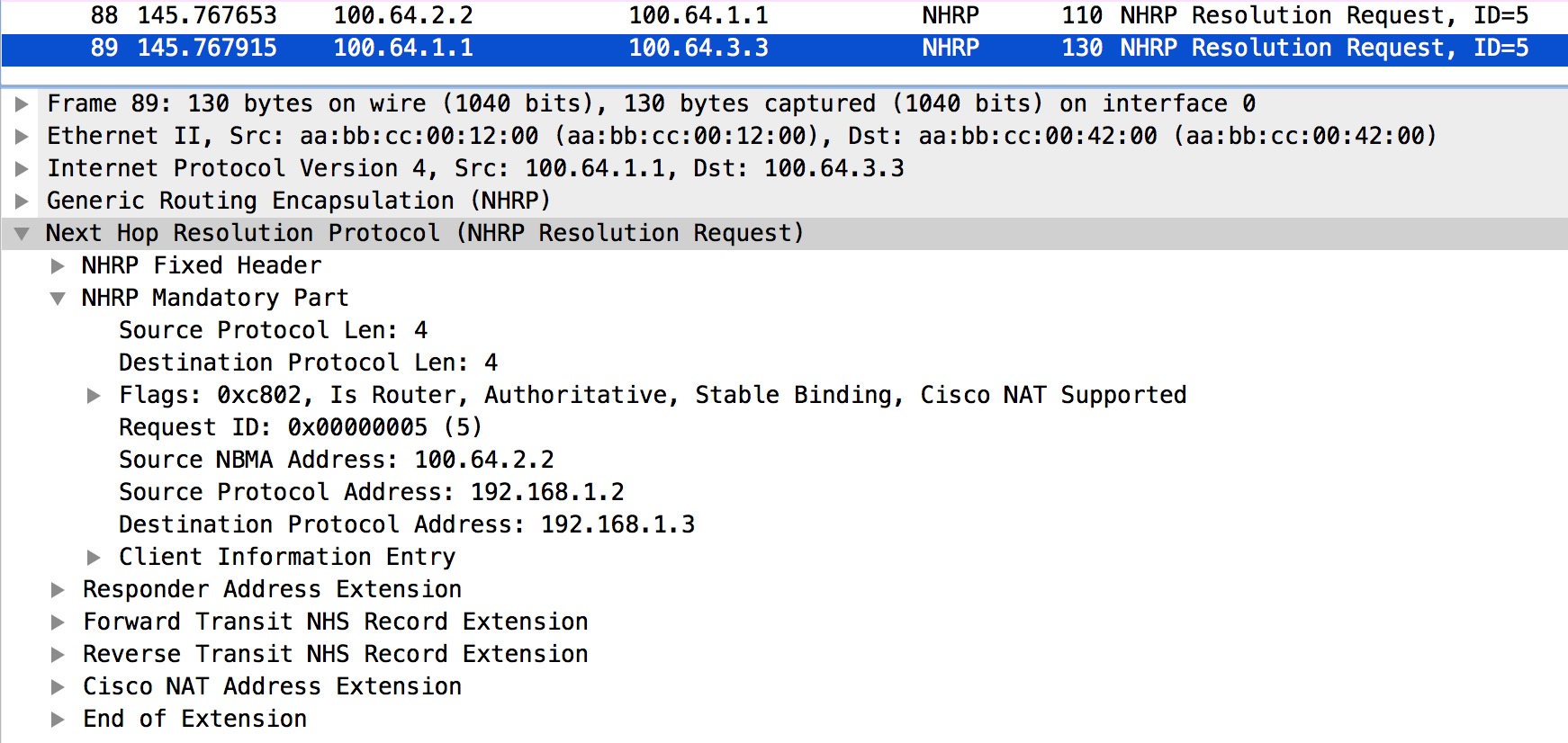
Again we look at the IP Src and Dst. Once again we’re confirming the theory of R1 forwarding the Request to R3.
Packet #88 is the original Resolution Request sent by R2. Packet #89 is the forwarded Resolution Request sent to R3.
The NHRP debug output on R3.
! R3 NHRP Debug output:
*Oct 20 09:39:15.204: NHRP: Receive Resolution Request via Tunnel0 vrf 0, packet size: 92
*Oct 20 09:39:15.204: (F) afn: AF_IP(1), type: IP(800), hop: 254, ver: 1
*Oct 20 09:39:15.204: shtl: 4(NSAP), sstl: 0(NSAP)
*Oct 20 09:39:15.204: pktsz: 92 extoff: 52
*Oct 20 09:39:15.204: (M) flags: "router auth src-stable nat ", reqid: 4
*Oct 20 09:39:15.204: src NBMA: 100.64.2.2
*Oct 20 09:39:15.204: src protocol: 192.168.1.2, dst protocol: 192.168.1.3
*Oct 20 09:39:15.204: (C-1) code: no error(0)
*Oct 20 09:39:15.204: prefix: 32, mtu: 17916, hd_time: 7200
*Oct 20 09:39:15.204: addr_len: 0(NSAP), subaddr_len: 0(NSAP), proto_len: 0, pref: 0
*Oct 20 09:39:15.204: NHRP: Send Resolution Reply via Tunnel0 vrf 0, packet size: 120
*Oct 20 09:39:15.204: src: 192.168.1.3, dst: 192.168.1.2
*Oct 20 09:39:15.204: (F) afn: AF_IP(1), type: IP(800), hop: 255, ver: 1
*Oct 20 09:39:15.204: shtl: 4(NSAP), sstl: 0(NSAP)
*Oct 20 09:39:15.204: pktsz: 120 extoff: 60
*Oct 20 09:39:15.204: (M) flags: "router auth dst-stable unique src-stable nat ", reqid: 4
*Oct 20 09:39:15.204: src NBMA: 100.64.2.2
*Oct 20 09:39:15.204: src protocol: 192.168.1.2, dst protocol: 192.168.1.3
*Oct 20 09:39:15.204: (C-1) code: no error(0)
*Oct 20 09:39:15.204: prefix: 32, mtu: 17916, hd_time: 7200
*Oct 20 09:39:15.204: addr_len: 4(NSAP), subaddr_len: 0(NSAP), proto_len: 4, pref: 0
*Oct 20 09:39:15.204: client NBMA: 100.64.3.3
*Oct 20 09:39:15.204: client protocol: 192.168.1.3
On R3 we see that the � NHRP Resolution Request� forwarded by R1 is received. This enables R3 to build a tunnel to R2. Also, a Resolution Reply is sent to R2, directly. Wireshark will tell us for sure:
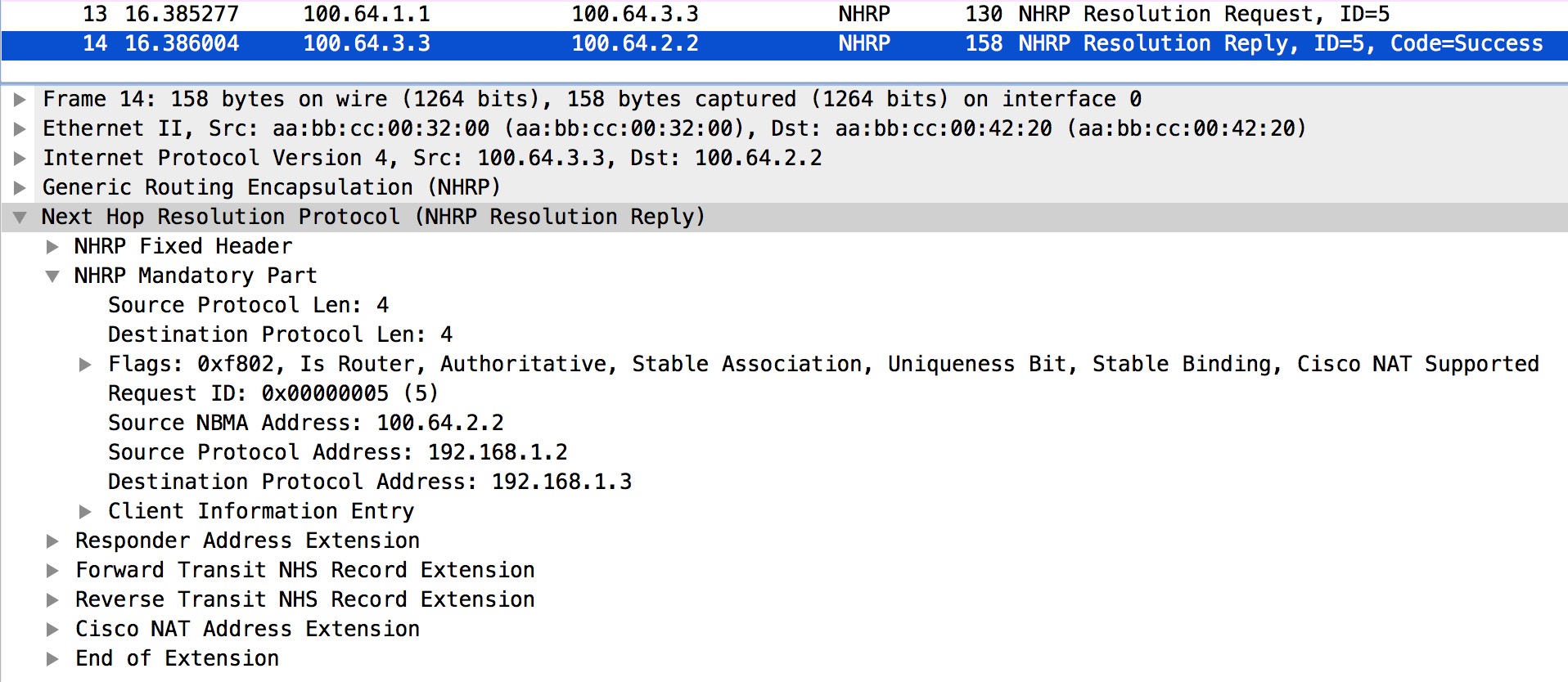
Packet #13 is the forwarded Resolution Request (originally from R2). Packet #14 is the actual Reply generated by R3 and sent directly to R2.
The NHRP debug output on R2 again.
! R2 NHRP Debug output:
*Oct 20 09:39:15.209: NHRP: Receive Resolution Reply via Tunnel0 vrf 0, packet size: 120
*Oct 20 09:39:15.209: (F) afn: AF_IP(1), type: IP(800), hop: 255, ver: 1
*Oct 20 09:39:15.209: shtl: 4(NSAP), sstl: 0(NSAP)
*Oct 20 09:39:15.209: pktsz: 120 extoff: 60
*Oct 20 09:39:15.209: (M) flags: "router auth dst-stable unique src-stable nat ", reqid: 4
*Oct 20 09:39:15.209: src NBMA: 100.64.2.2
*Oct 20 09:39:15.209: src protocol: 192.168.1.2, dst protocol: 192.168.1.3
*Oct 20 09:39:15.209: (C-1) code: no error(0)
*Oct 20 09:39:15.209: prefix: 32, mtu: 17916, hd_time: 7200
*Oct 20 09:39:15.209: addr_len: 4(NSAP), subaddr_len: 0(NSAP), proto_len: 4, pref: 0
*Oct 20 09:39:15.209: client NBMA: 100.64.3.3
*Oct 20 09:39:15.209: client protocol: 192.168.1.3
The NHRP Resolution Replay is received and now R2 can tunnel traffic to R3! Just to be sure, we’ll look at the NHRP Reply in the Wireshark capture on R2:

As promised, we’re looking at packet #18 on R2. This completes the NHRP Resolution process that takes the looped path from R2 -> R1 -> R3 -> R2.
Phase 3
DMVPN Phase 3 is the preferred way of configuring DMVPN when spoke to spoke traffic is required. This is because of its flexibility in regards to routing. I’ll elaborate on this later.
It introduces two new commands for NHRP. One for the hub and one for the spoke.
! R1 Hub Phase 3 Configuration:
interface Tunnel0
ip address 192.168.1.1 255.255.255.0
ip nhrp network-id 1
ip nhrp redirect
tunnel source Ethernet0/0
tunnel mode gre multipoint
! R2 Spoke Phase 3 Configuration:
interface Tunnel0
 ip address 192.168.1.2 255.255.255.0
 ip nhrp map 192.168.1.1 100.64.1.1
 ip nhrp network-id 1
 ip nhrp nhs 192.168.1.1
 ip nhrp shortcut
 tunnel source Ethernet0/0
 tunnel mode gre multipoint
So the ip nhrp redirect is configured on the hub and the ip nhrp shortcut is configured on spoke routers.
To demonstrate Phase 3, I’ve added a Loopback interface on R3 with the IP address 3.3.3.3/24. I have also summarized this network on R1 to advertise just the summary, 3.3.0.0/16. Let’s have a look at the routing table on R2 before we dive into the mystery of Phase 3:
! R2 Routing Table:
R2#sh ip route 3.3.3.3
Routing entry for 3.3.0.0/16
Known via "bgp 2", distance 20, metric 0
Tag 1, type external
Last update from 192.168.1.1 00:01:25 ago
Routing Descriptor Blocks:
* 192.168.1.1, from 192.168.1.1, 00:01:25 ago
Route metric is 0, traffic share count is 1
AS Hops 1
Route tag 1
MPLS label: none
R2#
So we’ve learned the 3.3.0.0/16 via BGP from R1 with a NH of R1. This means that R2 has no idea that 3.3.3.3 is reachable through R2! Now let’s take a dive into the flow of things.
We’ll start by pinging 3.3.3.3 from R2:
! R2 ping:
R2#ping 3.3.3.3
Type escape sequence to abort.
Sending 5, 100-byte ICMP Echos to 3.3.3.3, timeout is 2 seconds:
!!!!!
Success rate is 100 percent (5/5), round-trip min/avg/max = 1/1/2 ms
R2#
The Wireshark of first ping packet on R2 and NHRP redirect from R1:

Packet #29 is the original ICMP Echo request initiated by R2 towards R3 (3.3.3.3). Right after this we see packet #30 which is a NHRP Redirect traffic indication message from R1. Note this packet contains part of the original packet sent by R2 (the ICMP Echo request).
At R1 the ICMP Echo request is received like this:
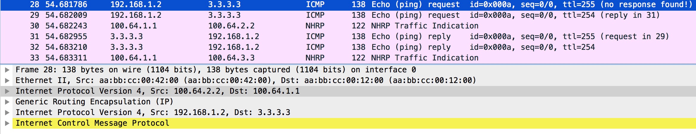
In Packet #28 we see the outer IP header with source 100.64.2.2 (R2) and destination 100.64.1.1 (R1) NBMA addresses. R1 does a lookup in its forwarding table and finds that R3 is the NH (Next Hop) out Tunnel0. Because Tunnel0 is enabled with NHRP, R1 checks the NHRP table to find the NBMA for R3:
! Lookups on R1
R1#sh ip cef 3.3.3.3
3.3.3.0/24
nexthop 192.168.1.3 Tunnel0
R1#
R1#sh ip nhrp 192.168.1.3
192.168.1.3/32 via 192.168.1.3
Tunnel0 created 01:14:05, expire 01:38:29
Type: dynamic, Flags: unique registered used nhop
NBMA address: 100.64.3.3
R1#
Next, R1 re-encapsulates the ICMP Echo request and forwards it to R3:
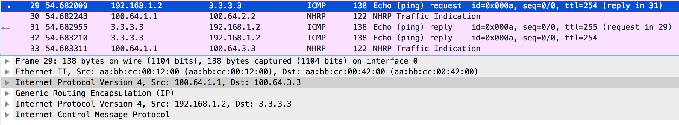
The important thing here is the outer IP header in packet #29 indicating R1 as the source (100.64.1.1) and R3 as the destination (100.64.3.3).
Packet #30 is the NHRP Redirect traffic indication we also see in packet #30 on R2.
Now, you does R3 reply to this ICMP Echo request? Let’s have a look:
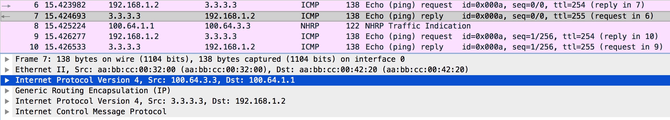
Firstly packet #6 is the ICMP Echo request from R2 that was sent by R1 as we found out. Packet #7 is the Echo reply from R3, but notice the outer IP header’s Src and Dst addresses. It is sent to R1! At this stage, R3 does not know about the NBMA address of R2, which is why it behaves this way.
Immediately after the reply is sent, R3 receives packet #8 – a NHRP Redirect traffic indication message from R1.
At this stage both R2 and R3 have received NHRP Redirect traffic indication messages from R1. This will cause both of them to do a NHRP Resolution Request. If we focus on R2 and have a look at the NHRP Resolution Request with the ID=8:

Here in packet #20, R2 asks for a mapping to 3.3.3.3 which was the destination address of the data packet contained in the redirect message (the original Ping Echo Request). This is what the ip nhrp shortcut config is there for on spoke routers.
Just like in Phase 2, the request goes to R1 that will forward it to R3. Let’s verify this behavior:
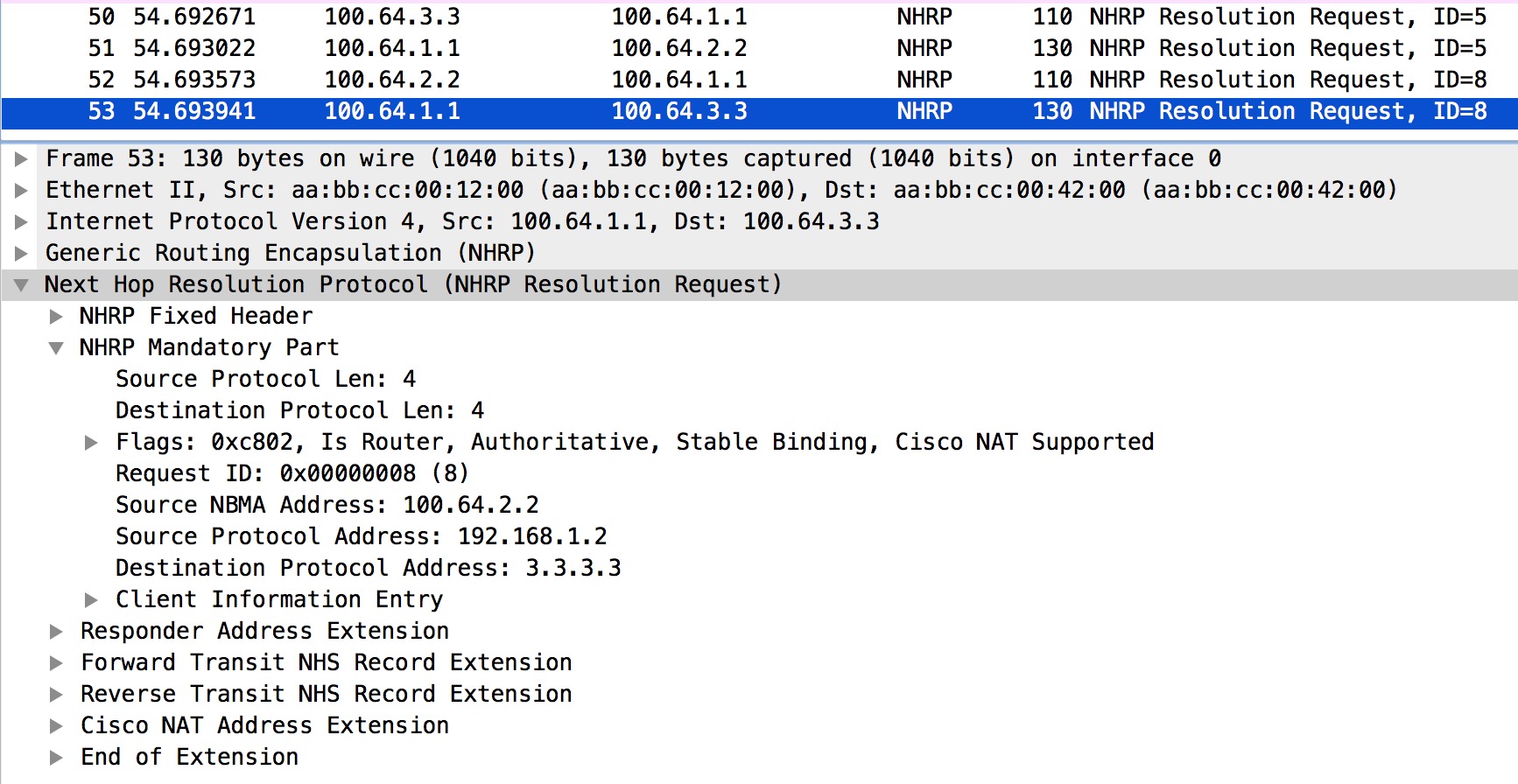
Again we look at the outer IP header and see that R1 is forwarding this to R3. The content of the NHRP Resolution Request (still ID=8) remains untouched. Packet #52 is the request received from R2.
Next let’s see what R3 will do with the Resolution Request:
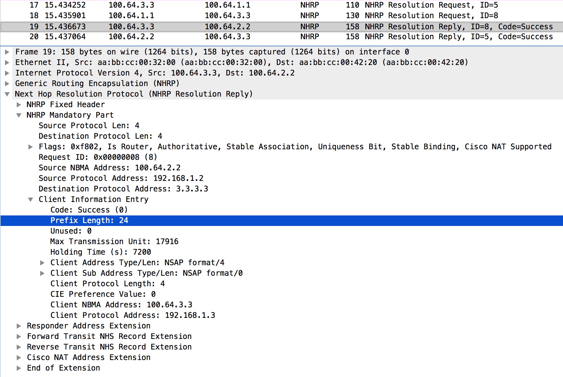
Very interestingly we see that R3 not only sends the Reply directly to R2 (outer IP header addresses) containing the Client NBMA for its own Client Protocol Address, but it also includes the Prefix Length of the requested 3.3.3.3 address. Now R2 knows that 3.3.3.0/24 is reachable via 192.168.1.3 out Tunnel0:
! R2 tables for 3.3.3.3
R2#sh ip route 3.3.3.3
Routing entry for 3.3.3.0/24
Known via "nhrp", distance 250, metric 1
Last update from 192.168.1.3 on Tunnel0, 01:00:46 ago
Routing Descriptor Blocks:
* 192.168.1.3, from 192.168.1.3, 01:00:46 ago, via Tunnel0
Route metric is 1, traffic share count is 1
MPLS label: none
R2#
R2#sh ip cef 3.3.3.3
3.3.3.0/24
nexthop 192.168.1.3 Tunnel0
R2#
R2#sh ip nhrp 3.3.3.0
3.3.3.0/24 via 192.168.1.3
Tunnel0 created 01:01:00, expire 00:58:59
Type: dynamic, Flags: router rib
NBMA address: 100.64.3.3
R2#
This is why with Phase 3 it is possible to summarize on the Hub. You could even send just a default route down to the spoke routers!
I did not explain who R3 also did a NHRP Resolution Request. Remember that R1 also sent R3 the NHRP Redirect traffic indication message? This causes R3 to send a NHRP Resolution Request asking for the mapping of the destination address of the original data packet in the NHRP Redirect message. In this setup this seems unnecessary, because R3 already knows about the NBMA of the source of R2 when I received the NHRP Resolution Request originated by R2 (sent through R1). But had the ping from R2 been sourced from a Loopback on R2, this NHRP Resolution Request sent by R3 would make sense.
Cisco also has a document describing DMVPN Phase 3