mVPN – Profile 0 aka. “Rosen Draft”
mVPN Profile 0 is the original way of doing mVPN when we had no extensions to LDP. This means we need PIM in the underlay – the SP core. Specifically the profile is called:
Profile 0 Default MDT - GRE - PIM C-mcast Signaling
Topology
I’ll use the following topology to go through and explain the concepts and workings of Rosen Draft with Data MDT.
Default MDT
MDT (Multicast Distribution Tree) is referring to the SPs global environment – the underlay. And the Default MDT is what is used to connect the PEs together in a LAN like NBMA fashion where every PE will become PIM neighbors with all other PEs. We need the Default MDT to provide the underlay for the customers multicast traffic that travels inside the mVRF (multicast VRF).
To be able to join the Default MDT the PEs need the sources of every other PEs. How does the PE know the source IPs of the other PEs? We use BGP IPv4 MDT for the signaling of the (S,G) that should be joined for the Default MDT. SSM is the only viable solution with the Default MDT although you could do ASM, but why would you? So the configuration in the cores is really simple:
! P routers
ip multicast-routing distributed
ip pim ssm default
!
int x/y
 ip pim sparse-mode
! PE routers
ip multicast-routing distributed
ip multicast-routing vrf x distributed
ip pim ssm default
!
int x/y
 ip pim sparse-mode
!
int Loopback0
 ip pim sparse-mode
!
router bgp 65000
 neighbor rr peer-group
 neighbor rr remote-as 65000
 neighbor rr update-source Loopback0
 neighbor 3.3.3.3 peer-group rr
 !
 address-family vpnv4
  neighbor rr send-community extended
  neighbor 3.3.3.3 activate
 exit-address-family
 !
 address-family ipv4 mdt
  neighbor 3.3.3.3 activate
 exit-address-family
 !
 address-family ipv4 vrf a
  redistribute connected metric 0
 exit-address-family
! RR
router bgp 65000
 neighbor rr-client peer-group
 neighbor rr-client remote-as 65000
 neighbor rr-client update-source Loopback0
 neighbor 2.2.2.2 peer-group rr-client
 neighbor 4.4.4.4 peer-group rr-client
 !
 address-family vpnv4
  neighbor rr-client send-community extended
  neighbor rr-client route-reflector-client
  neighbor 2.2.2.2 activate
  neighbor 4.4.4.4 activate
 exit-address-family
 !
 address-family ipv4 mdt
  neighbor rr-client route-reflector-client
  neighbor 2.2.2.2 activate
  neighbor 4.4.4.4 activate
 exit-address-family
On the PE routers you will need the regular RP configuration or SSM configuration in the mVRF.
When you configure the Default MDT group in the VRF, a MTI (Multicast Tunnel Interface) is created. It is of type mGRE using the VPNv4 update-source as the source interface and it is also unnumbered to this interface. Here is what the configuration looks like:
interface Tunnel0
 ip unnumbered Loopback0
 no ip redirects
 ip mtu 1500
 tunnel source Loopback0
 tunnel mode gre multipoint
Although we can’t see that the tunnel is a member of a VRF from the derived-config, it is clearly seen when viewing the VRF:
R4#sh vrf
  Name         Default RD            Protocols   Interfaces
  a            4.4.4.4:10            ipv4        Gi1.46
                                                 Tu0
It is a bit like having a backdoor VRF with a DMVPN tunnel interface and the underlay (source) in global (no frontdoor VRF).
The VRF is configured like this:
! VRF a on R4
vrf definition a
 rd 4.4.4.4:10
 route-target export 65000:10
 route-target import 65000:10
 !
 address-family ipv4
  mdt default 232.1.0.10
  mdt data 232.1.1.0 0.0.0.255 threshold 1
  mdt data threshold 1
 exit-address-family
Ignore the mdt data part for now. We see the mdt default configuration with the group 232.1.0.10. You must use uniq groups per VRF.
To join the other PEs we need their addresses. This is received using BGP IPv4 MDT:
R4#sh bgp ipv4 mdt all 2.2.2.2/32
BGP routing table entry for 2.2.2.2:10:2.2.2.2/32 version 2
Paths: (1 available, best #1, table IPv4-MDT-BGP-Table)
  Not advertised to any peer
  Refresh Epoch 2
  Local
    2.2.2.2 from 3.3.3.3 (3.3.3.3)
      Origin incomplete, metric 0, localpref 100, valid, internal, best
      Originator: 2.2.2.2, Cluster list: 3.3.3.3,
      MDT group address: 232.1.0.10

      rx pathid: 0, tx pathid: 0x0
R4#
Here we see an update that originated from R2 and was reflected by R3. It has a next-hop matching its VPNv4 update-source which is Loopback0 with an IP address of 2.2.2.2/32. Also it contains the MDT group address 232.1.0.10 for the Default MDT. Now we can join the Default/MDT. This information is used by PIM:
R4#sh ip pim mdt bgp
MDT (Route Distinguisher + IPv4)    Router ID    Next Hop
  MDT group 232.1.0.10
   4.4.4.4:10:2.2.2.2               3.3.3.3      2.2.2.2
R4#
And we can see in the multicast routing table (in global) that we in fact did join the Default MDT:
R4#sh ip mroute 232.1.0.10
IP Multicast Routing Table
Flags: s - SSM Group
T - SPT-bit set,
I - Received Source Specific Host Report,
Z - Multicast Tunnel

(4.4.4.4, 232.1.0.10), 00:00:30/00:02:59, flags: sT
  Incoming interface: Loopback0, RPF nbr 0.0.0.0
  Outgoing interface list:
    GigabitEthernet1.34, Forward/Sparse, 00:00:30/00:02:59
(2.2.2.2, 232.1.0.10), 00:28:51/stopped, flags: sTIZ
  Incoming interface: GigabitEthernet1.34, RPF nbr 10.0.34.3
  Outgoing interface list:
    MVRF a, Forward/Sparse, 00:28:51/00:01:08

R4#
This should give us a PIM neighbor over the MTI in VRF a:
R4#sh ip pim vrf a nei
PIM Neighbor Table
Mode: B - Bidir Capable, DR - Designated Router, N - Default DR Priority,
      P - Proxy Capable, S - State Refresh Capable, G - GenID Capable,
      L - DR Load-balancing Capable
Neighbor        Interface             Uptime/Expires    Ver   DR
Address                                                            Prio/Mode
2.2.2.2         Tunnel0               00:02:29/00:01:43 v2    1 / S P G
R4#
A bit like Layer 3 MPLS VPNs where we transit the SP core using the global table.� So the customer multicast traffic in the overlay travels over the MTI which uses the Default MDT (the underlay).
At this point we have no mroute entries in VRF a, but the network is ready to serve the customers multicast traffic via the Default MDT.
Data MDT
Why do we need a Data MDT? Well, the Default MDT is joined by all PEs, meaning that all PEs will receive all multicast packets. This is not very efficient and reminds us of the old days where we had PIM dense mode. The idea of the Data MDT is that once a certain threshold� (in kbps) is passed, the ingress PE (so the PE with the source behind it) will send a PIM� Data-MDT Join message over the Default MDT so all egress PEs receive it. The message contains (S,G,MDT) where MDT is a new multicast group taken from a range of addresses specified under the VRF. In this case that would be 232.1.1.0/24.
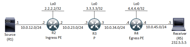
The PIM Data-MDT Join message looks like this:
So the destination is the All PIM Routers address 224.0.0.13 of the inner IP packet. Its a UDP packet and the Data part should hold the (S,G,MDT) information. The outer IP header uses the Default MDT group address as destination.
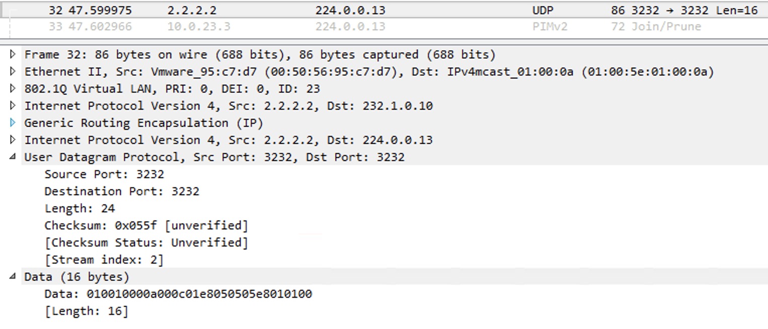
Immediately we receive a PIM Join message initiate by the egress PE. This is sent upstream towards the ingress PE. It looks like this:
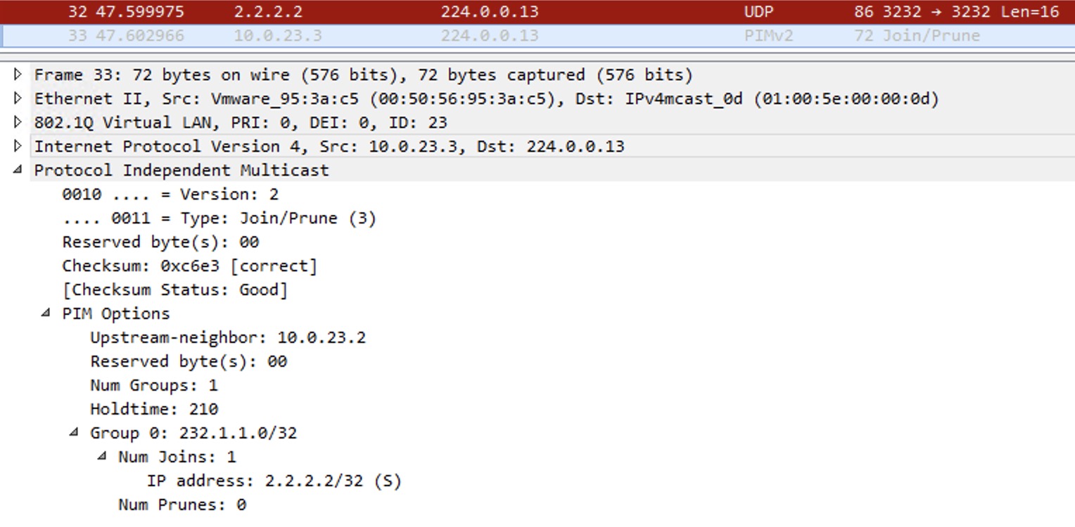
After 3 seconds the ingress PE stops sending the stream on the Default MDT and now sends it only over the Data MDT, meaning that only those egress PEs with receivers behind them will receive the traffic. Here is the wireshark to confirm this:
The Data-MDT Join in the top (red) was at time 47.59. The next ICMP Echo sent is at 49.18 which isn’t after the 3 seconds, so this was sent over the Default MDT. Now the highlighted packet shows the new Data MDT Group which is 232.1.1.0 (the first available IP in the Data MDT range). The switchover has happened and the Default MDT is no longer used for this communication to 232.5.5.5 (the inner multicast destination – the customer packet).
The PEs that currently do not have receivers behind them, will cache the Data-MDT Join information for fast signaling if a receiver should send a report requesting the stream.
Data MDT groups can be reused. They time out after a period of inactivity.
MPLS
As the profile name says we’re using GRE to transport the customers traffic across the SP core. Actually the packet is multicast in multicast. NO MPLS is used in the forwarding of multicast! But why do we need MPLS then? Well, multicast relies heavily on RPF (Reverse Path Forwarding) check to avoid loops and duplicate packets. So for the mVRF we must have a unicast IP address for RPF checks. For this we use normal Layer 3 MPLS VPNs that does require MPLS.
RPF
RPF in the mVRF can be a bit confusing. Here I’m thinking about how the egress PE (so the PE with receivers behind it) does RPF check when the multicast stream is received on the MTI.
R4#sh ip rpf vrf a 10.0.12.1
RPF information for ? (10.0.12.1)
  RPF interface: Tunnel0
  RPF neighbor: ? (2.2.2.2)
  RPF route/mask: 10.0.12.0/24
  RPF type: unicast (bgp 65000)
  Doing distance-preferred lookups across tables
  BGP originator: 2.2.2.2
  RPF topology: ipv4 multicast base, originated from ipv4 unicast base
R4#
The MTI isn’t used for unicast routing. So the RPF check for the customer source prefix will not use the MTI as the RPF interface hence RPF will fail. To go about this unfortunate situation, the RPF interface is set to the MTI that is associated with that mVRF. And if the RPF interface is set to the MTI, the RPF neighbor is set to the customer source (VPNv4 prefix) BGP next-hop which is the ingress PE. This next-hop must also be the PIM neighbor in the mVRF table.